
01
Material and joint
Provide alloy, coating, thickness, joint type, seam length, access and target penetration/fusion.
Laser Welding | FLW Series
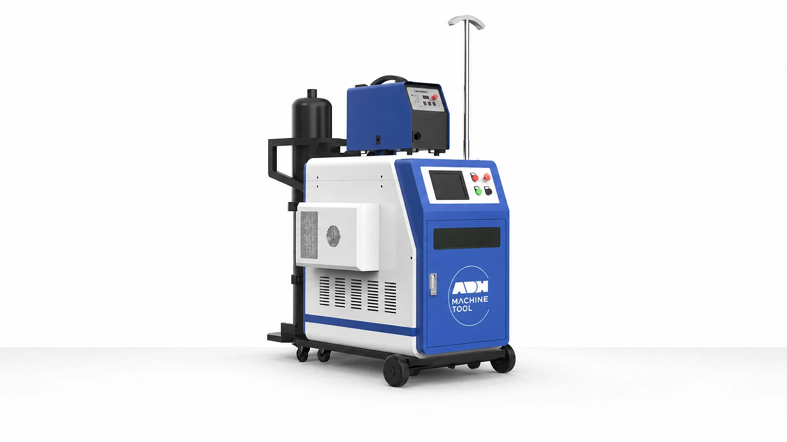
Handheld fiber-laser welding with configurable source, oscillating head, wire feed and cooling for your joint requirements.
Technical specifications
FLW laser sources are rated from 1,000 to 3,000 W. Source output instability is below 3% under the specified test conditions of 25°C and at least 5 hours of continuous operation. Use a trial weld on your material to check joint quality.
| Model | Rated Output | Operating Mode | Output Pattern | Power Adjustment | Centre Wavelength | Source Output Instability | Modulation Frequency | Red-Light Output | Beam Quality (BPP) | Numerical Aperture | Fibre Core | Output Fibre Length |
|---|---|---|---|---|---|---|---|---|---|---|---|---|
| Unit | W | % | nm | Hz | mW | µm | m | |||||
| FLW | 1000–3000 | Continuous / modulated | Variable multi-point oscillation | 10–100 | 1080 | <3% at 25°C during ≥5 h of continuous operation | 50–5k | 0.5–1 | <2 | 0.2 | 50 · 25/100/200 optional | 10 |
Welding inputs
Power alone does not define a weld. Review material, joint, fit-up, filler, access, duty and inspection together.
01
Provide alloy, coating, thickness, joint type, seam length, access and target penetration/fusion.
02
Record gap, edge preparation, wire, bead appearance, distortion and strength/leak criteria.
03
Define power, gas, cooling, fibre length, extraction and electrical supply.
04
Confirm controlled access, reflection hazards, training, PPE, fume extraction and sample coupon.
Machine in operation
Watch the FLW welding sequence, then compare the source, head, process control and cooling systems below.
Watch on YouTube (opens in a new tab)Product systems
The FLW setup combines a laser source, handheld head, process control and cooling. Select it around the material, joint access and required weld result, together with the planned workstation.
Laser source
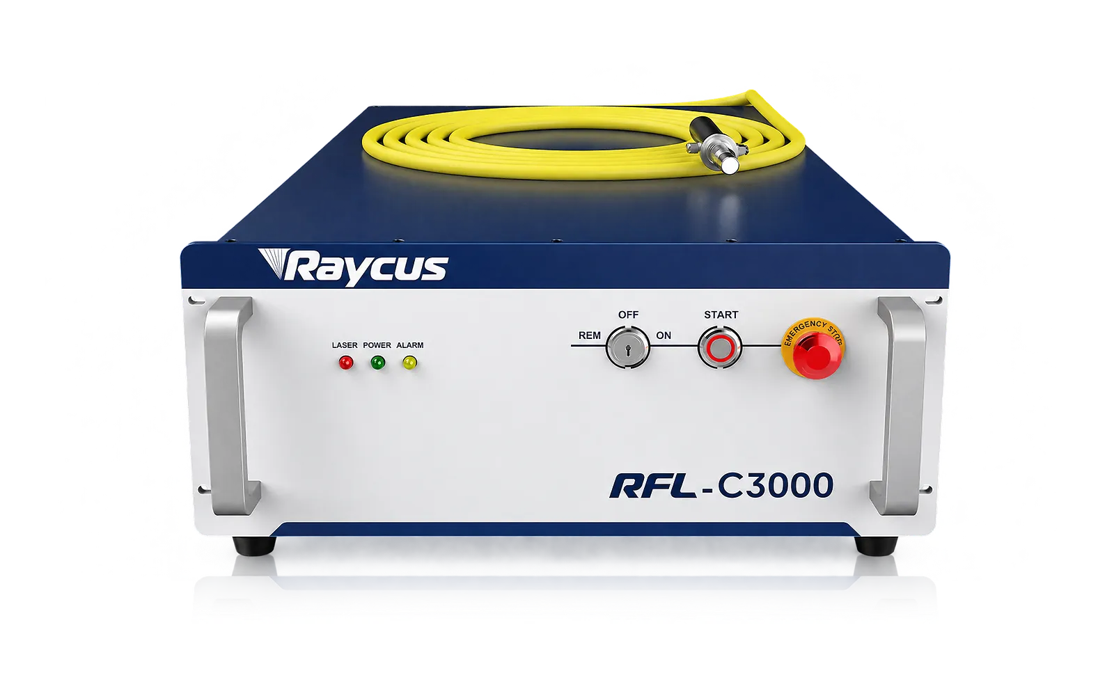
The FLW range lists 1000–3000 W sources with continuous or modulated operation.
Choose power against the intended material and joint, then validate the result with a weld sample.
Fibre delivery
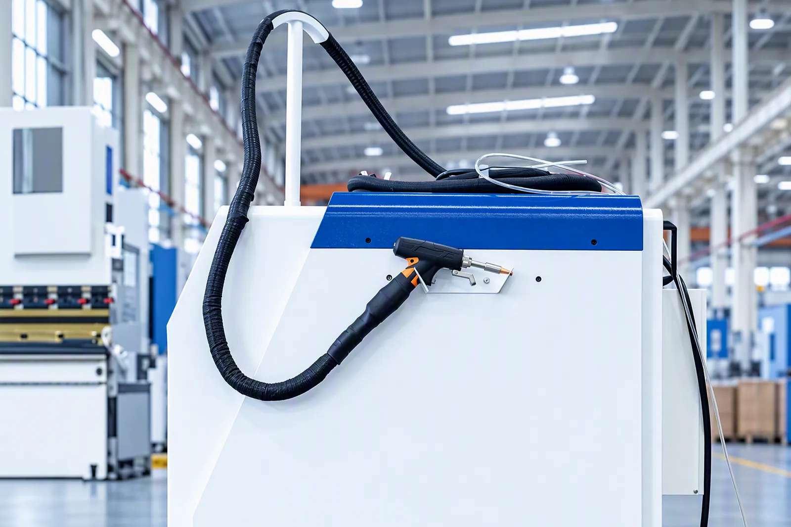
The fibre package delivers the source output to the handheld head.
Match fibre core and cable length to the selected machine and workstation.
02
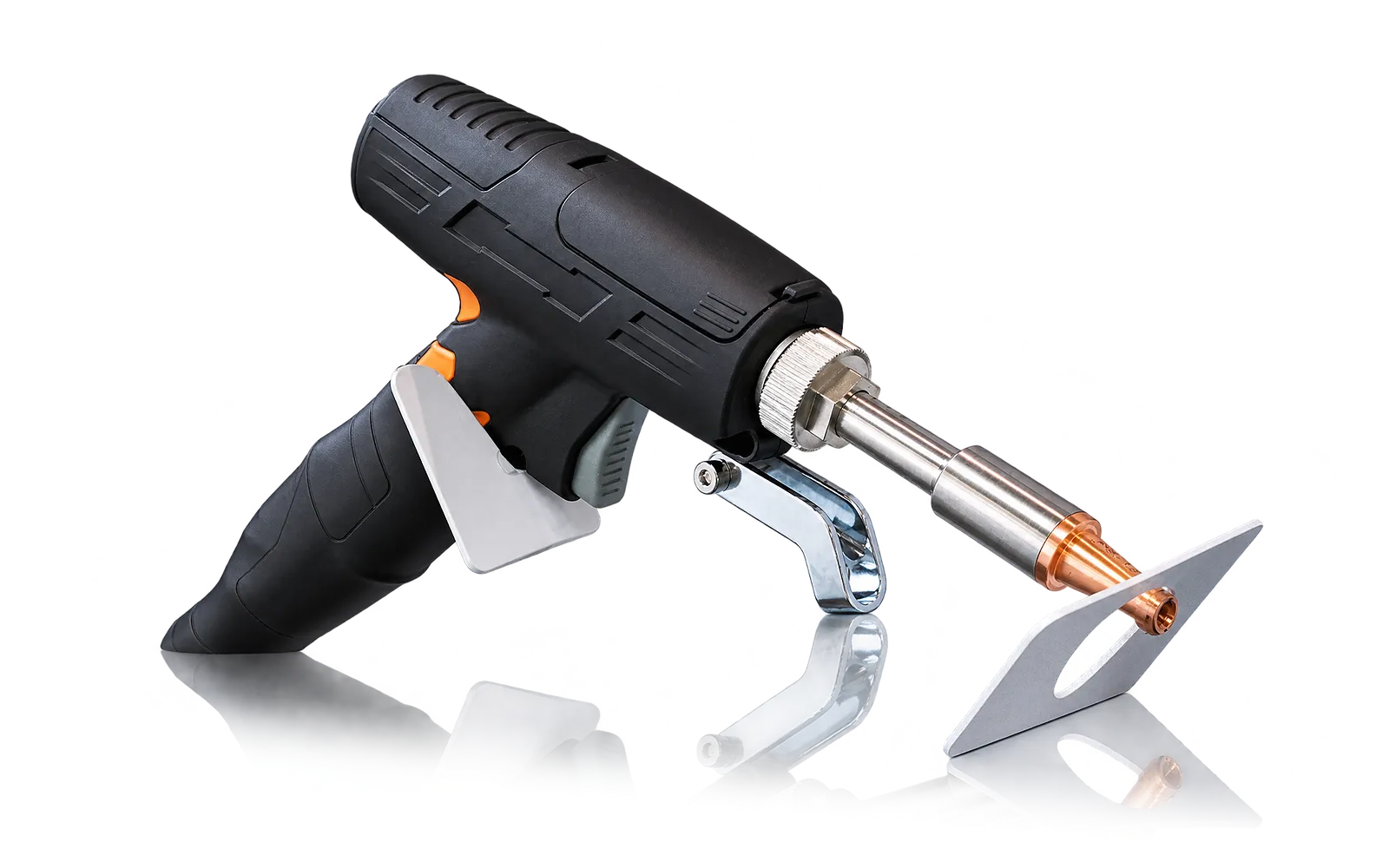
The handheld head combines beam oscillation, nozzle positioning and shielding-gas delivery at the joint. Head access affects how the operator can follow the seam.
Review nozzle, optics, joint access and the intended material. Oscillation settings and the process recipe belong to the selected head and welding package.
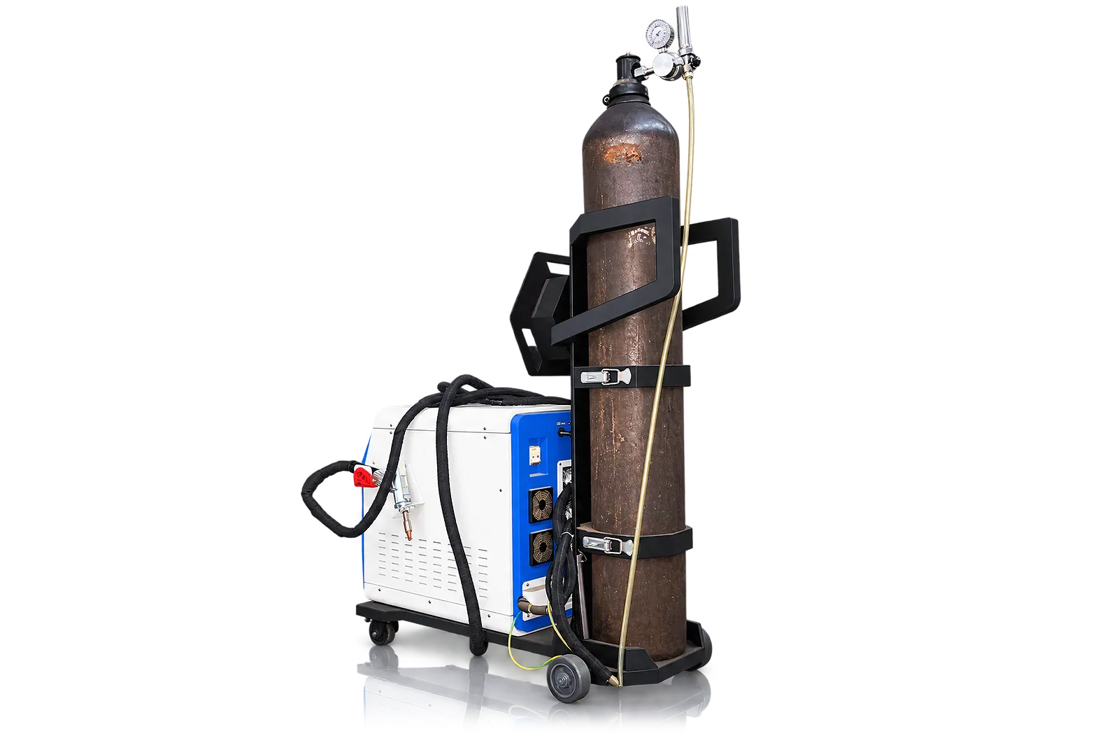
Shielding gas
Shielding gas forms part of the welding recipe at the joint.
Select the gas and parameter range for the intended joint and supplied package.
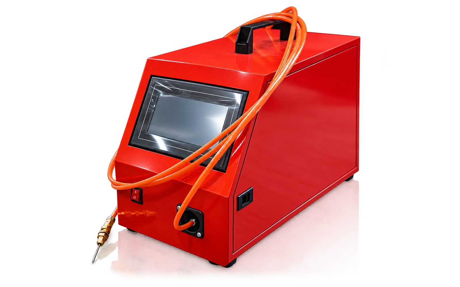
Wire feeding
The 2026 FLW configuration uses a four-roll, dual-drive automatic wire feeder for 0.8–1.6 mm filler wire.
Select the filler alloy and wire diameter for the joint. Retraction at weld stop and a programmable feed delay coordinate the wire with the weld cycle.
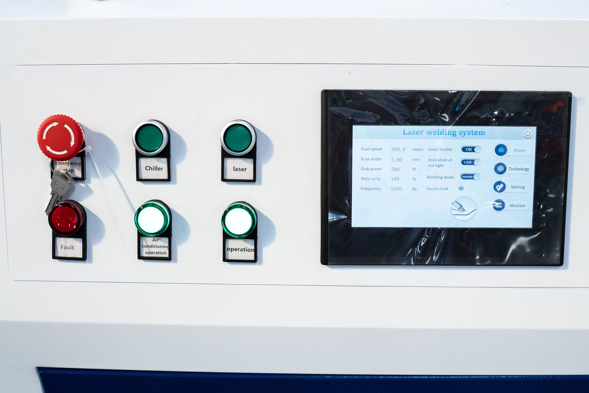
Process control
The controller coordinates laser output and oscillation with gas and any wire feeding.
Review stored recipes and which control functions are included in the machine.
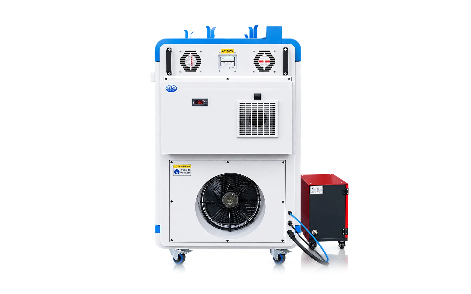
04
The 2026 FLW configuration has an integrated industrial water chiller with two temperature-control circuits for the laser source and optics.
Check the ordered source power, ambient temperature and cooling connections when sizing the workstation.
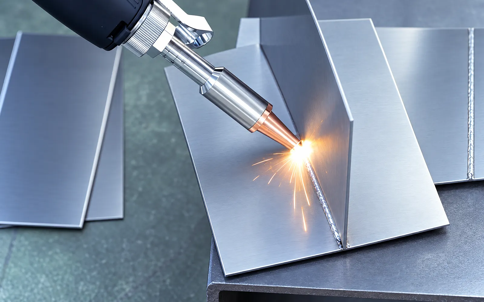
Workstation
Plan the working area, extraction and controlled access around the intended process.
Define site responsibilities alongside the supplied equipment and installation scope.
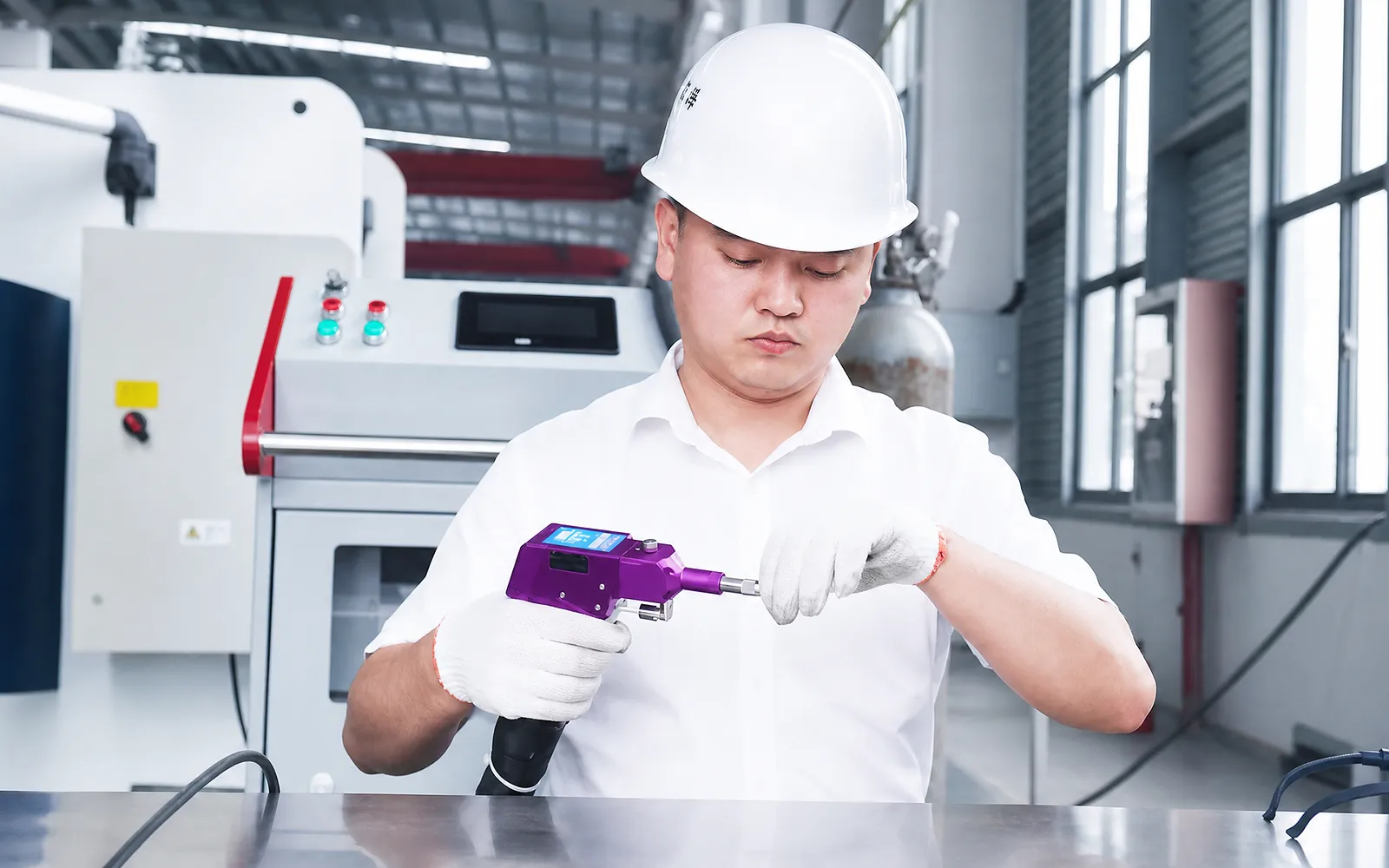
Operator protection
Handpiece safety functions, interlocks, protective equipment and training form part of the installation review.
Confirm the supplied functions and operator requirements for the intended work.
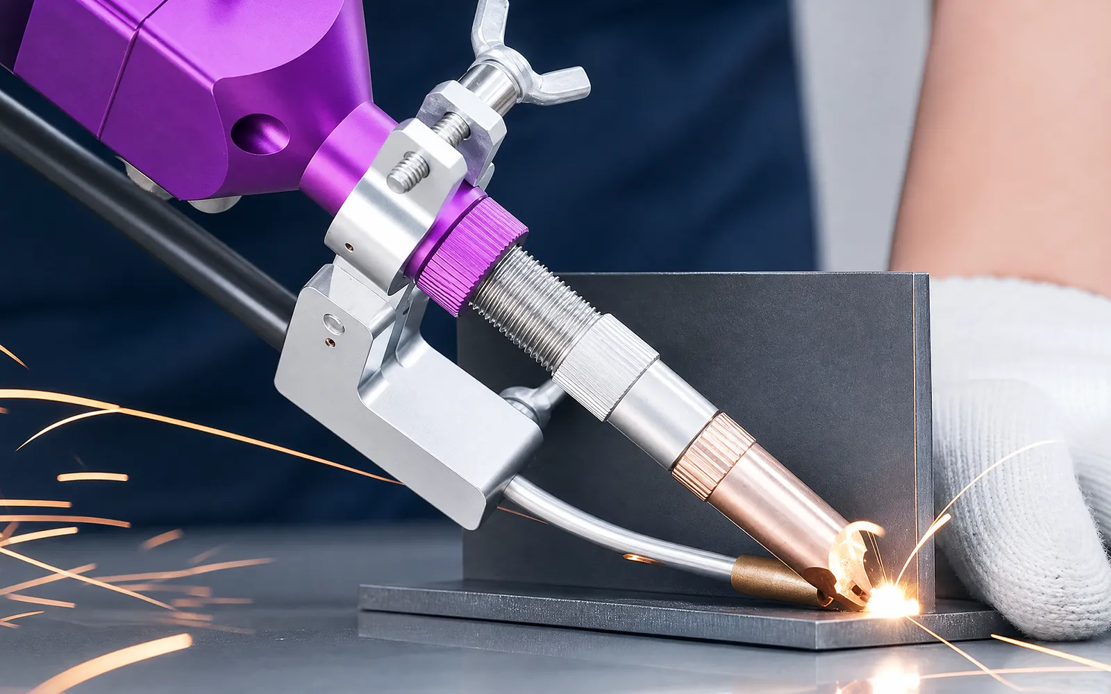
06
A representative seam brings the source, head, wire or no-wire process, gas and operator access together. Inspect the weld against the intended joint requirement.
Agree material, joint preparation and the visual or measured acceptance criteria. Evaluate the delivered recipe and workstation conditions used for the trial.
Process and safety boundary
Set the welding process for your alloy, joint and fit-up, then verify it on a representative sample.
Use the FLW parameter table for rated power, mode, adjustment, wavelength, modulation, optical and fibre values.
Source, cooling, head, spot mode, wire feeder, optics, gas and enclosure depend on the selected process.
Approve coupons for material, joint, gap, penetration, appearance and inspection, then complete the laser-safety assessment.
Related machines & selection
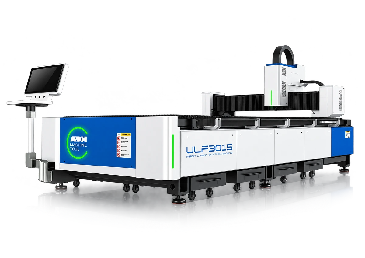
Through the machine lifecycle
Find the training, maintenance guidance and parts support your team needs. Services and availability are confirmed for your machine and location.
Before start-up
Prepare utilities, lifting and the installation area, then coordinate start-up and handover.
Review installation supportBefore production
Build the operator, programming and maintenance skills required for your delivered machine.
Explore trainingIn operation
Get support with the machine model, serial number and a clear description of the issue.
Request technical supportPlanned spares
Identify your machine and component so our team can check compatibility and availability.
Request service or partsSelf-service
Find video guidance for operating and maintaining your ADH machine. Check relevance to your model and configuration.
Browse support videosContract scope
Your quotation or contract defines included services, warranty, exclusions and responsibilities.
Review service scopeProject enquiry
Tell us what you want to make or improve. Technical details and drawings can follow.
Contact ADH
Name, email and a short description are enough to begin.