
01
Part and bend plan
Provide drawings, material, thickness, blank size, bend sequence, tolerances and the part families intended for automatic production.
Robotic Bending | WADG-FMC
A configurable cell coordinates a CNC press brake, robot, grippers, referencing, reorientation and stacking around the part family and production sequence.
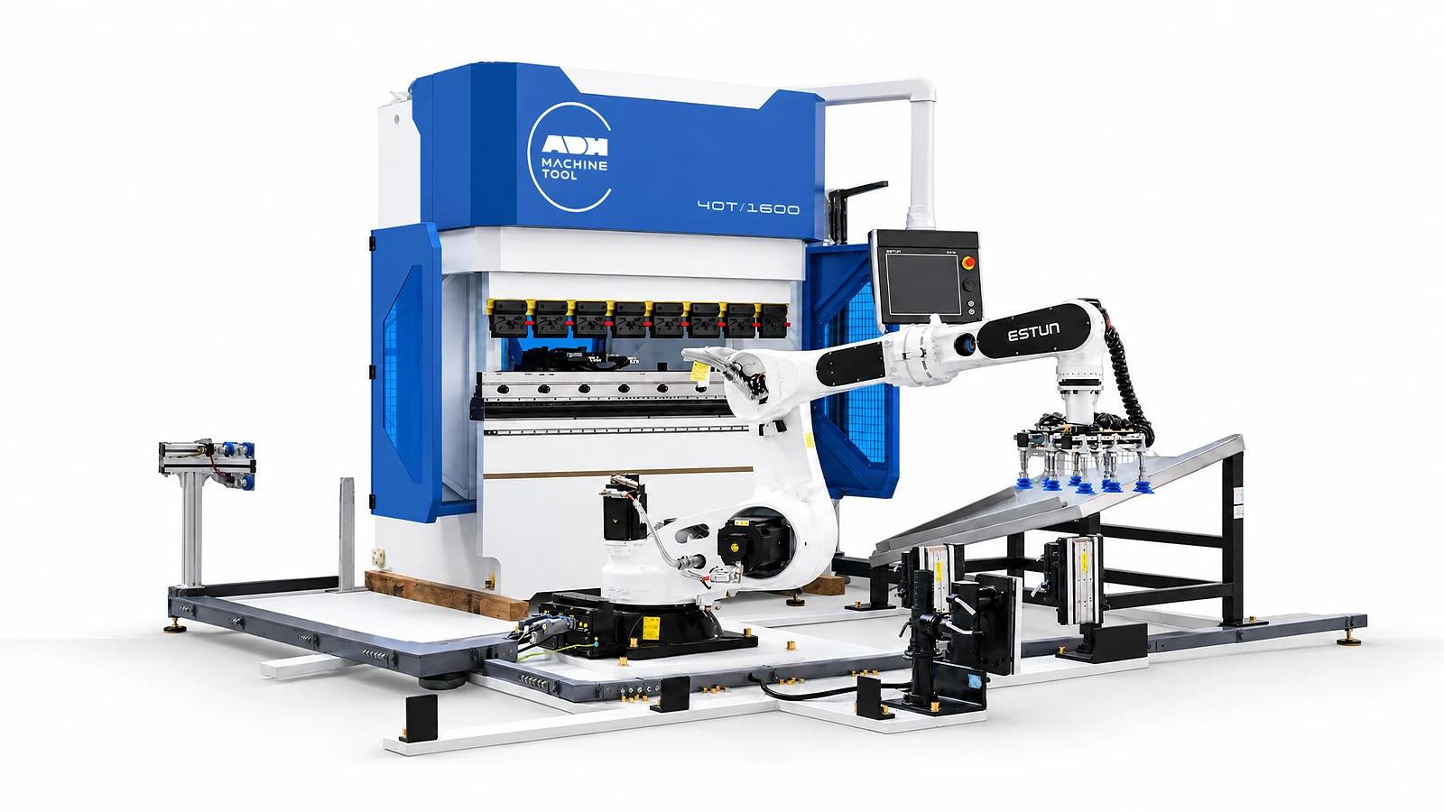
Host-machine reference
The table gives the force, working length and motion limits of each WADG press used as a cell host. For the robotic cell, size the robot for the combined part and gripper weight at its furthest reach. Check the bend sequence for regripping, turnover and tool clearance before setting the cycle-time target.
| Model | Bending Force | Working Length | Approach Speed | Working Speed | Return Speed | X Stroke | X Speed | R Stroke | R Speed | Column Distance | Throat Depth | Ram Stroke | Open Height | Main Motor | Weight | Overall Dimensions |
|---|---|---|---|---|---|---|---|---|---|---|---|---|---|---|---|---|
| Unit | kN | mm | mm/s | mm/s | mm/s | mm | mm/s | mm | mm/s | mm | mm | mm | mm | kW | t | L×W×H mm |
| WADG-10T/500 | 100 | 500 | 180 | 0.15-30 | 180 | 200 | 400 | 80 | 200 | 510 | 200 | 150 | 420 | 6 | 0.8 | 640*980*1250 |
| WADG-20T/800 | 200 | 800 | 250 | 0.15-30 | 250 | 400 | 500 | 150 | 200 | 780 | 250 | 150 | 420 | 15 | 3.1 | 1200*1560*2450 |
| WADG-30T/1250 | 300 | 1250 | 250 | 0.15-30 | 250 | 400 | 500 | 150 | 200 | 900 | 250 | 150 | 420 | 20 | 4.1 | 1460*1660*2470 |
| WADG-40T/1300 | 400 | 1300 | 250 | 0.15-30 | 250 | 400 | 500 | 150 | 200 | 920 | 255 | 150 | 420 | 2X15 | 4.5 | 1700*2050*2280 |
| WADG-40T/1600 | 400 | 1600 | 250 | 0.15-30 | 250 | 400 | 500 | 150 | 200 | 1120 | 255 | 150 | 420 | 2X15 | 4.9 | 1700*2050*2280 |
| WADG-50T/1600 | 500 | 1600 | 250 | 0.15-30 | 250 | 400 | 500 | 150 | 200 | 1250 | 255 | 200 | 470 | 2×20 | 4.9 | 2200*2050*2280 |
| WADG-60T/2000 | 600 | 2000 | 250 | 0.15-30 | 250 | 500 | 500 | 150 | 200 | 1600 | 300 | 200 | 470 | 2X20 | 6 | 2700*2150*2380 |
| WADG-80T/2500 | 800 | 2500 | 200 | 0.15-30 | 200 | 500 | 500 | 150 | 200 | 2000 | 460 | 200 | 470 | 2X25 | 8.9 | 3000*2250*2380 |
| WADG-100T/3200 | 1000 | 3200 | 200 | 0.15-30 | 200 | 500 | 500 | 150 | 200 | 2700 | 460 | 200 | 470 | 2X25 | 10.7 | 4000*2450*2580 |
| WADG-160T/3200 | 1600 | 3200 | 200 | 0.15-30 | 200 | 500 | 500 | 150 | 200 | 2700 | 460 | 250 | 520 | 3X25 | 11.8 | 4000*2450*2780 |
Automation inputs
Robot reach and payload are only starting points; grip, reorientation, stations, safety and acceptance must be designed as one workflow.
01
Provide drawings, material, thickness, blank size, bend sequence, tolerances and the part families intended for automatic production.
02
Define part weight, flexibility, surface, pickup zones, stack condition, centring, flips and every required regrip.
03
Record batch mix, changeover, target operating window, finished-part stack pattern and the recovery method for interruptions.
04
Confirm host press brake, robot, grippers, stations, data handshakes, guarded perimeter and the full-cycle acceptance test.
Machine in operation
Watch the 165T/3200 bending-cell demonstration, then review pickup, bend sequence, regripping and unloading for your own part family.
Watch on YouTube (opens in a new tab)Product systems
Follow the part from blank pickup to finished-part transfer. Robot reach, gripping, part references and the press-brake sequence must fit the same part family.
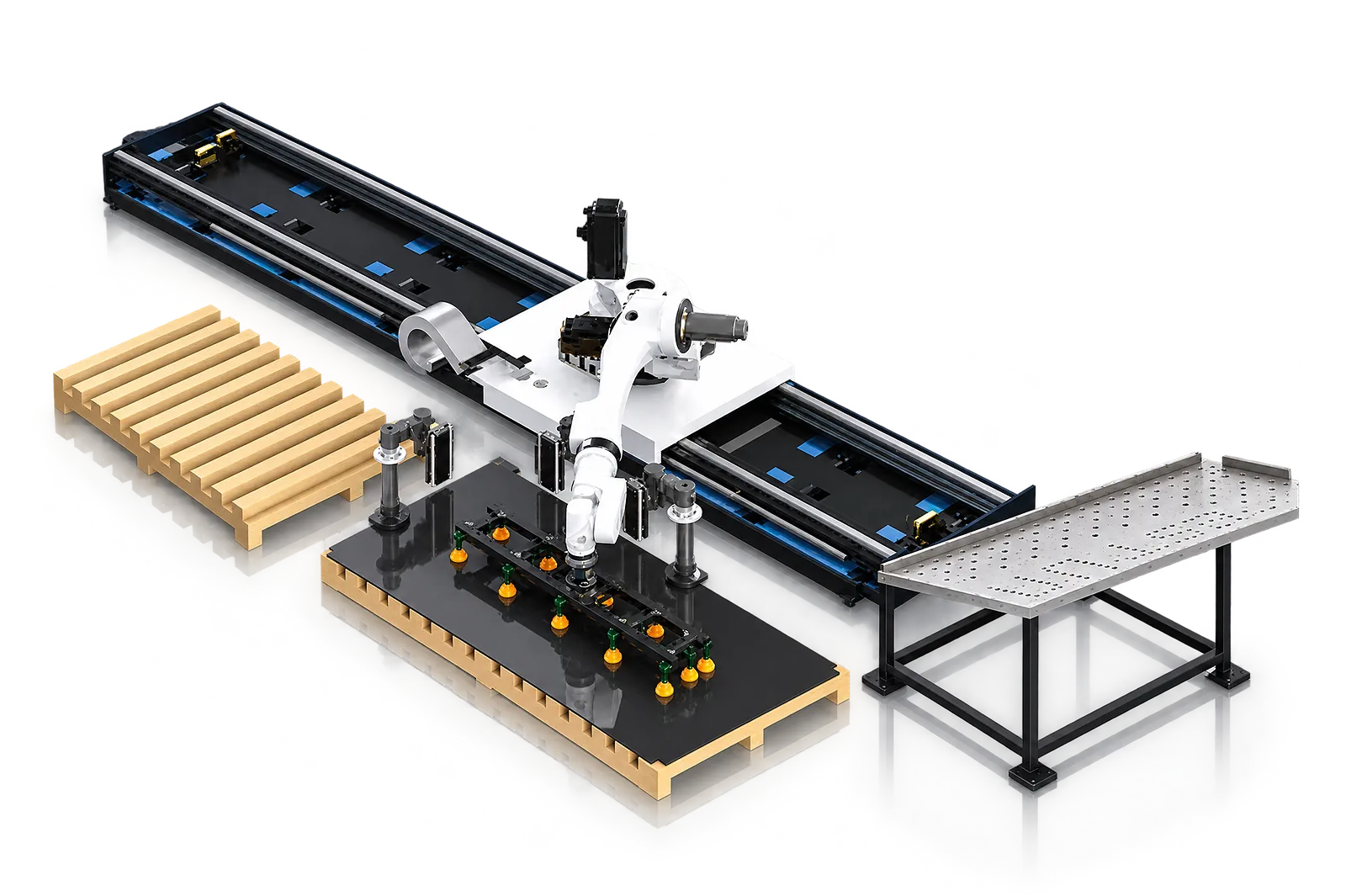
Blank pickup
The robot collects a blank from the defined loading position using a gripper suited to the application.
Review payload, reach, pickup zones and surface protection.
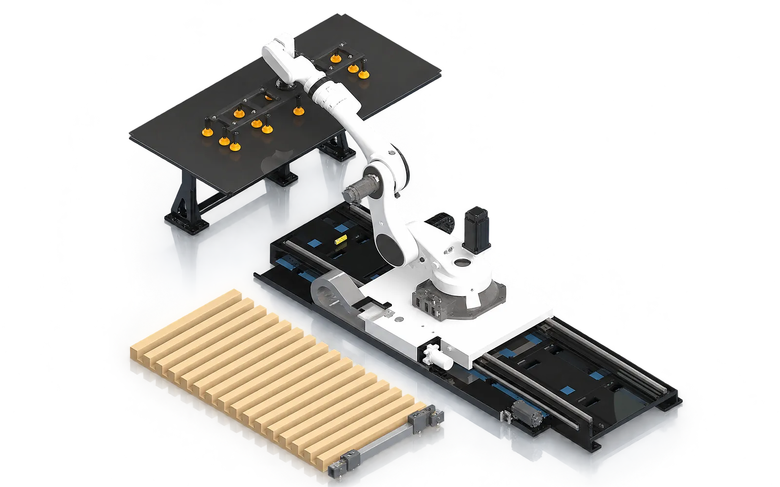
Blank separation
Separation checks depend on sheet geometry, material and stack condition.
Confirm the loading equipment and any double-sheet detection for the application.
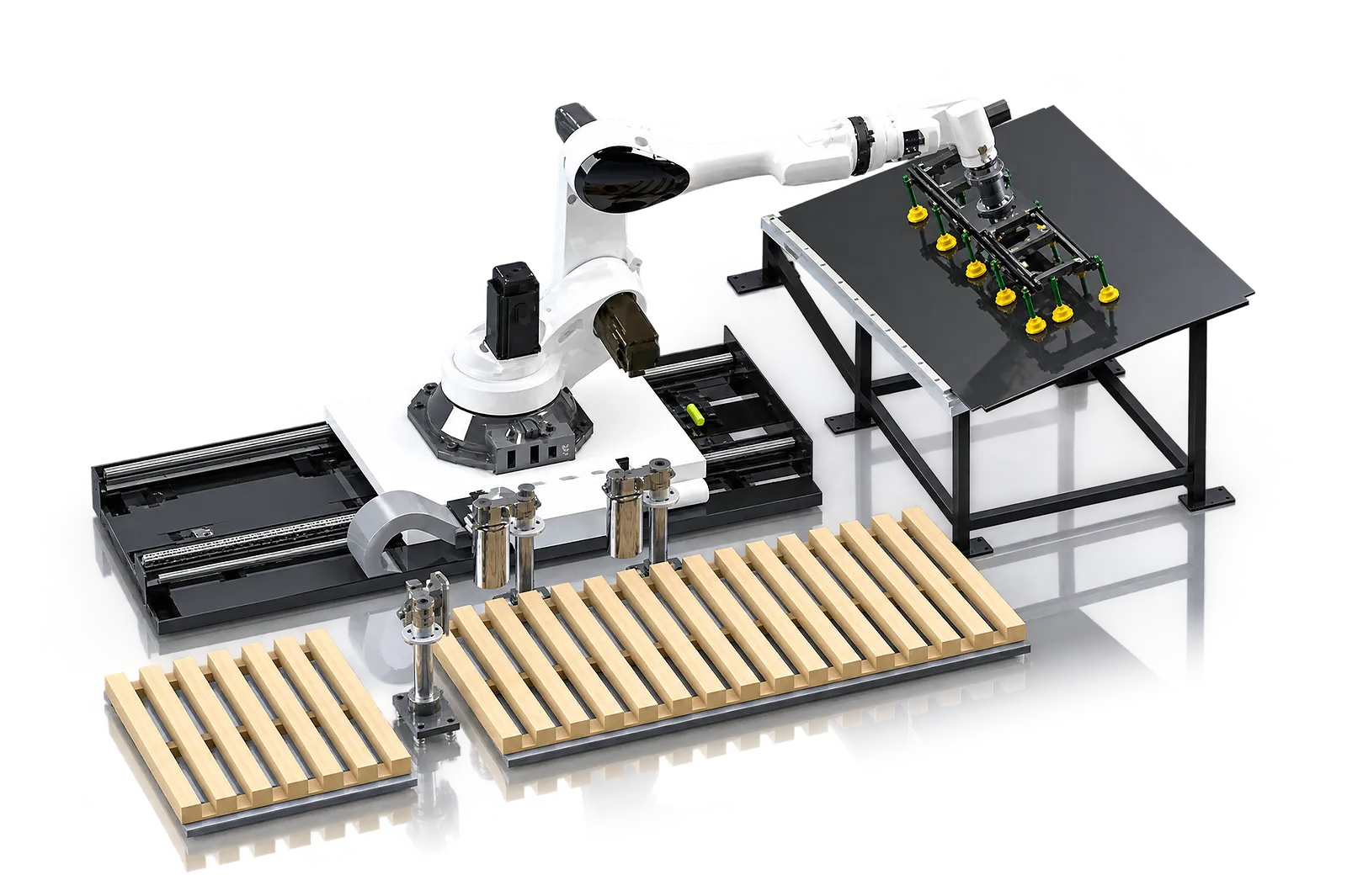
Part referencing
A centring station can establish the part reference before bending.
Review the defined position from which the robot presents the workpiece.
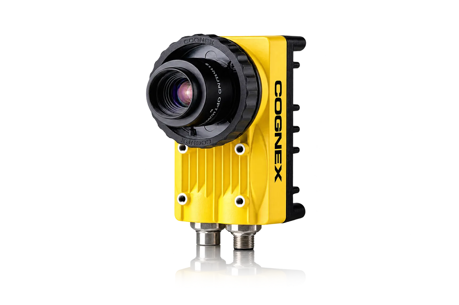
Optional vision
A configured vision system can establish the reference from the part features.
Test camera, lighting, features and correction range on the actual part family.
03
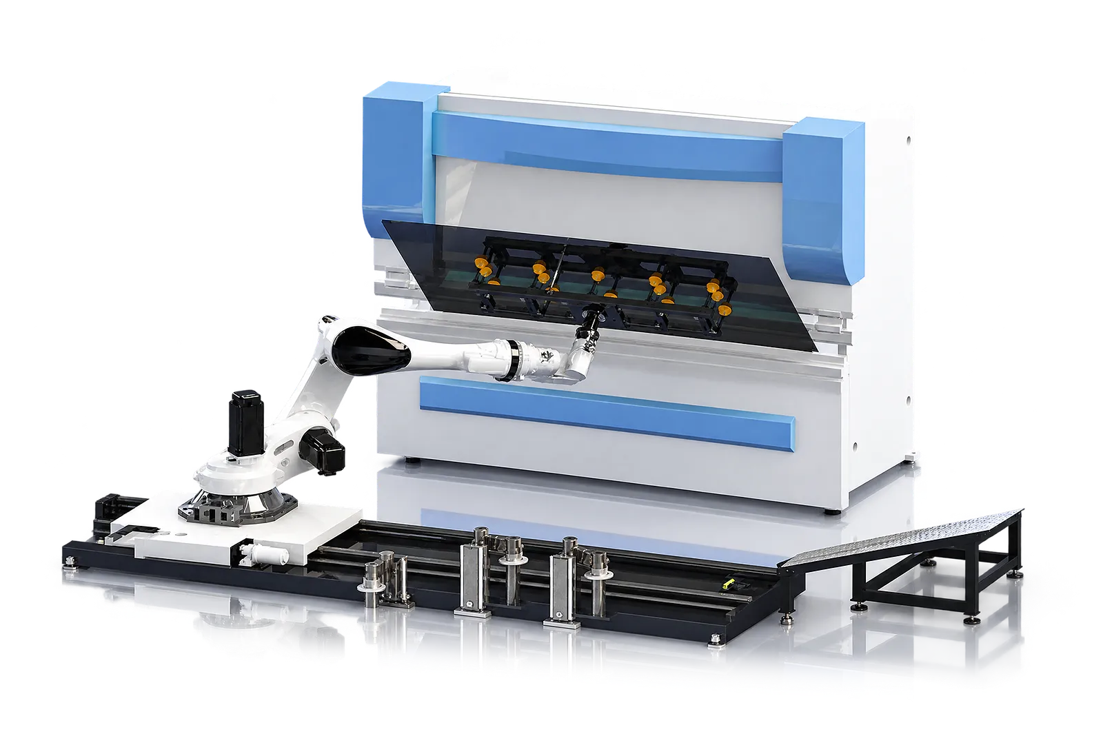
The press brake positions its backgauge while the robot presents and reorients the workpiece through the bend sequence. Gripper clearance and robot motion are programmed around the geometry.
Review access at every bend, potential collisions and any follower behavior. The host-machine specification describes the press brake; it is not a complete-cell rating.
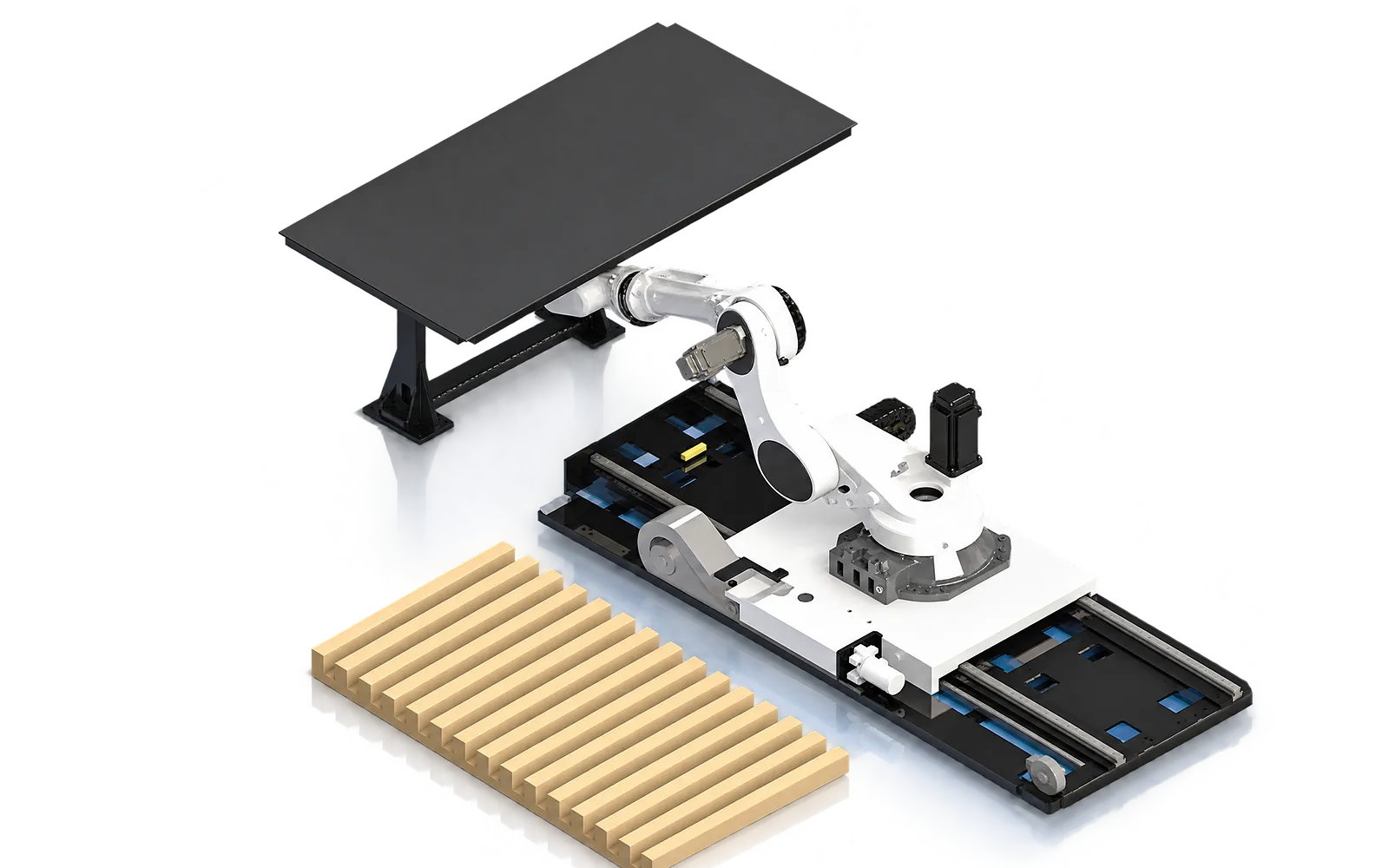
Regripping
Flip frames, regripping stations or gripper changes allow different faces to reach the bending tools.
Select the required modules from the part family and bend sequence.
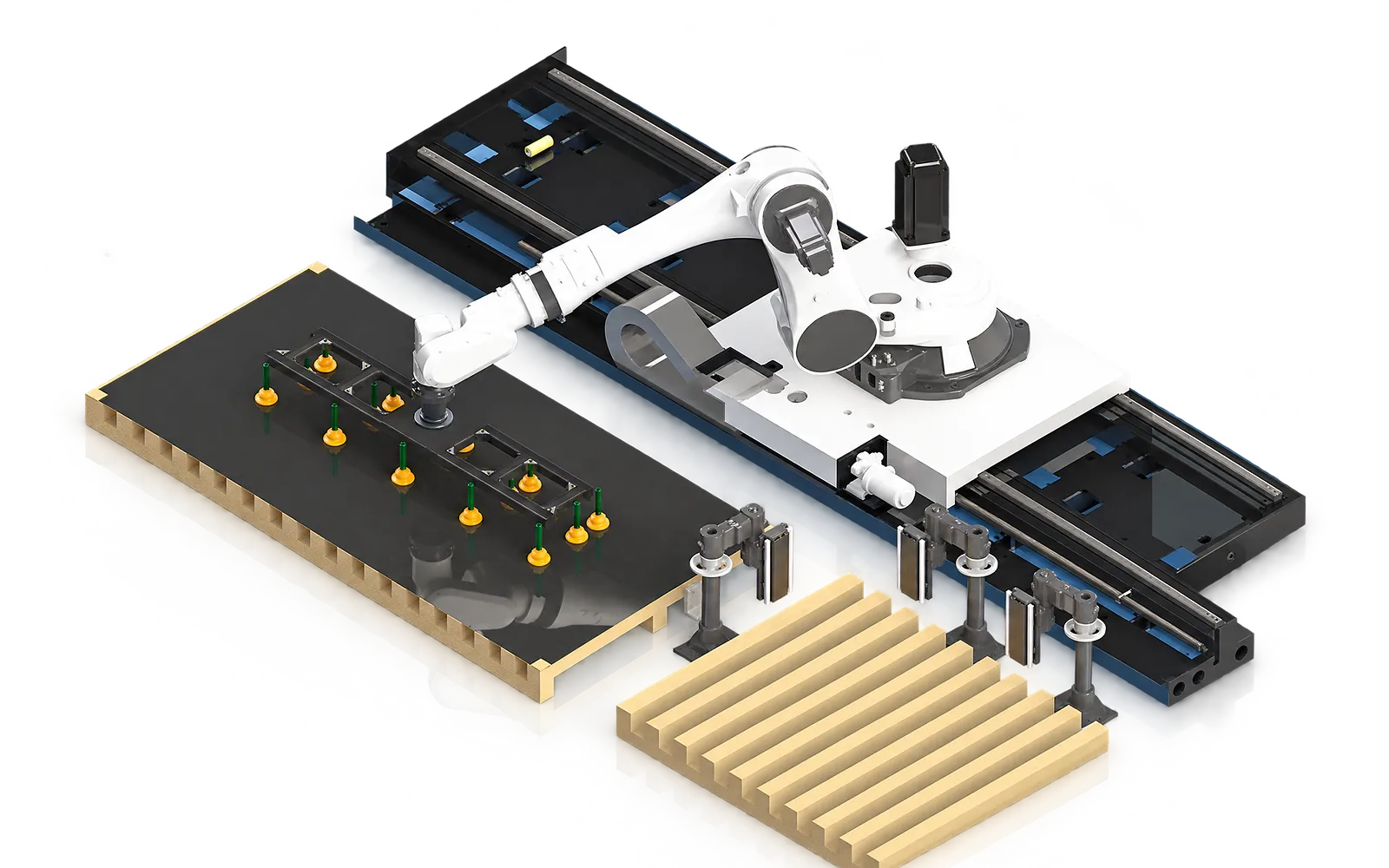
Finished-part transfer
The output arrangement determines how completed parts are placed or stacked.
Include finished-part access and the required handling handoffs in the cell layout.
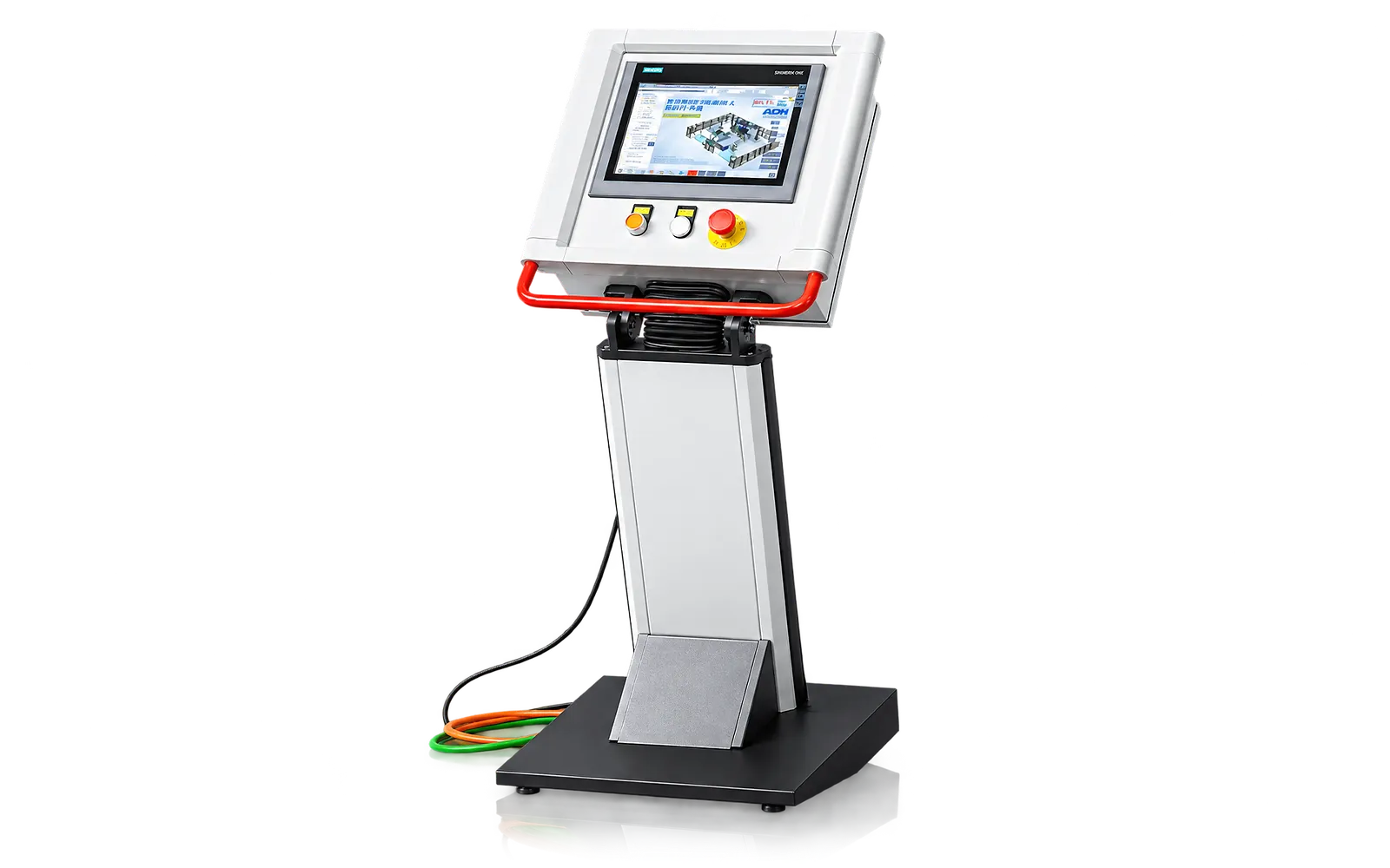
Cell control
The robot, press brake and handling stations need agreed handshakes for loading, bending and transfer.
Specify the equipment interfaces and operating states for the complete cell.
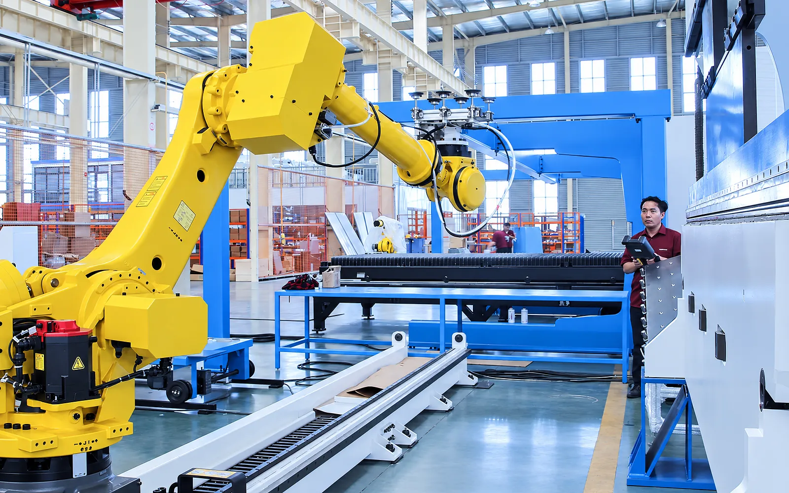
Recovery
Recovery states define how an operator resolves a stopped or incomplete sequence.
Review guarding, safety stops and intervention points, including their effect on returning to production.
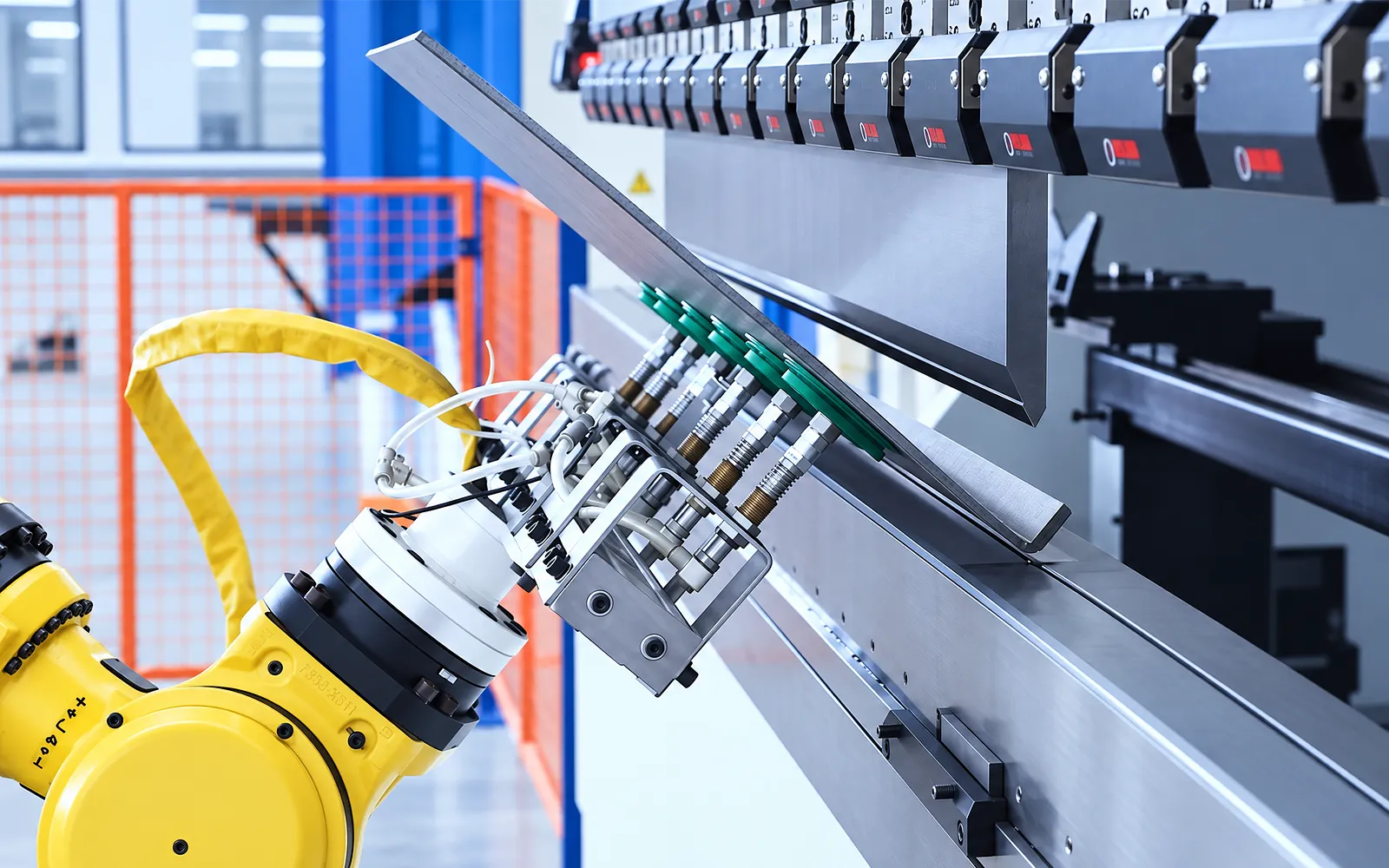
06
A representative job set exercises pickup, referencing, bending, regripping and output. Include changeovers and recovery so the review covers the complete production cycle.
Agree drawings, material, inspection points and interface tests. Assess the cell result separately from the published host-machine data.
Cell configuration
The WADG parameter data describes the host press brake, not the total cell.
The cell can combine a press brake, six-axis robot and selected loading, centring, flipping, unloading and guarding modules.
Payload, reach, track, grippers, detection, stations, quick change, MES/ERP, AGV and safety devices follow the part and layout.
Footprint, operating window, recovery, interfaces, cycle study and full-cell acceptance require a dedicated project document.
Related machines & selection
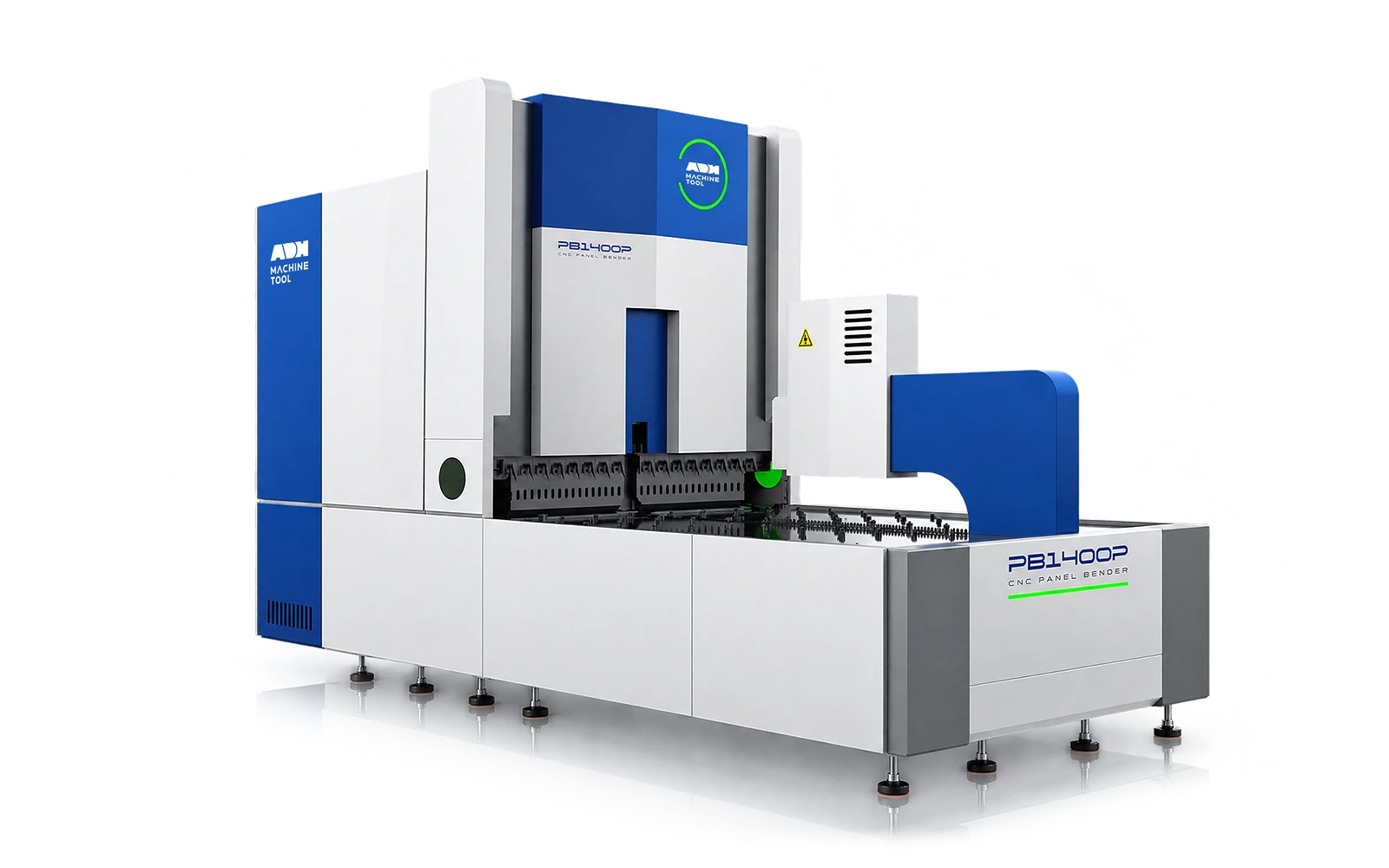
Through the machine lifecycle
Find the training, maintenance guidance and parts support your team needs. Services and availability are confirmed for your machine and location.
Before start-up
Prepare utilities, lifting and the installation area, then coordinate start-up and handover.
Review installation supportBefore production
Build the operator, programming and maintenance skills required for your delivered machine.
Explore trainingIn operation
Get support with the machine model, serial number and a clear description of the issue.
Request technical supportPlanned spares
Identify your machine and component so our team can check compatibility and availability.
Request service or partsSelf-service
Find video guidance for operating and maintaining your ADH machine. Check relevance to your model and configuration.
Browse support videosContract scope
Your quotation or contract defines included services, warranty, exclusions and responsibilities.
Review service scopeSee equipment options for the parts your industry produces.
Project enquiry
Tell us what you want to make or improve. Technical details and drawings can follow.
Contact ADH
Name, email and a short description are enough to begin.