
Best for
Press-brake operator work-area control
Press Brake Upgrade
Pedal, wireless module, machine module, monitoring, display and charging must work with the machine and safety platform. Confirm range and safe-state behavior in the installed environment.
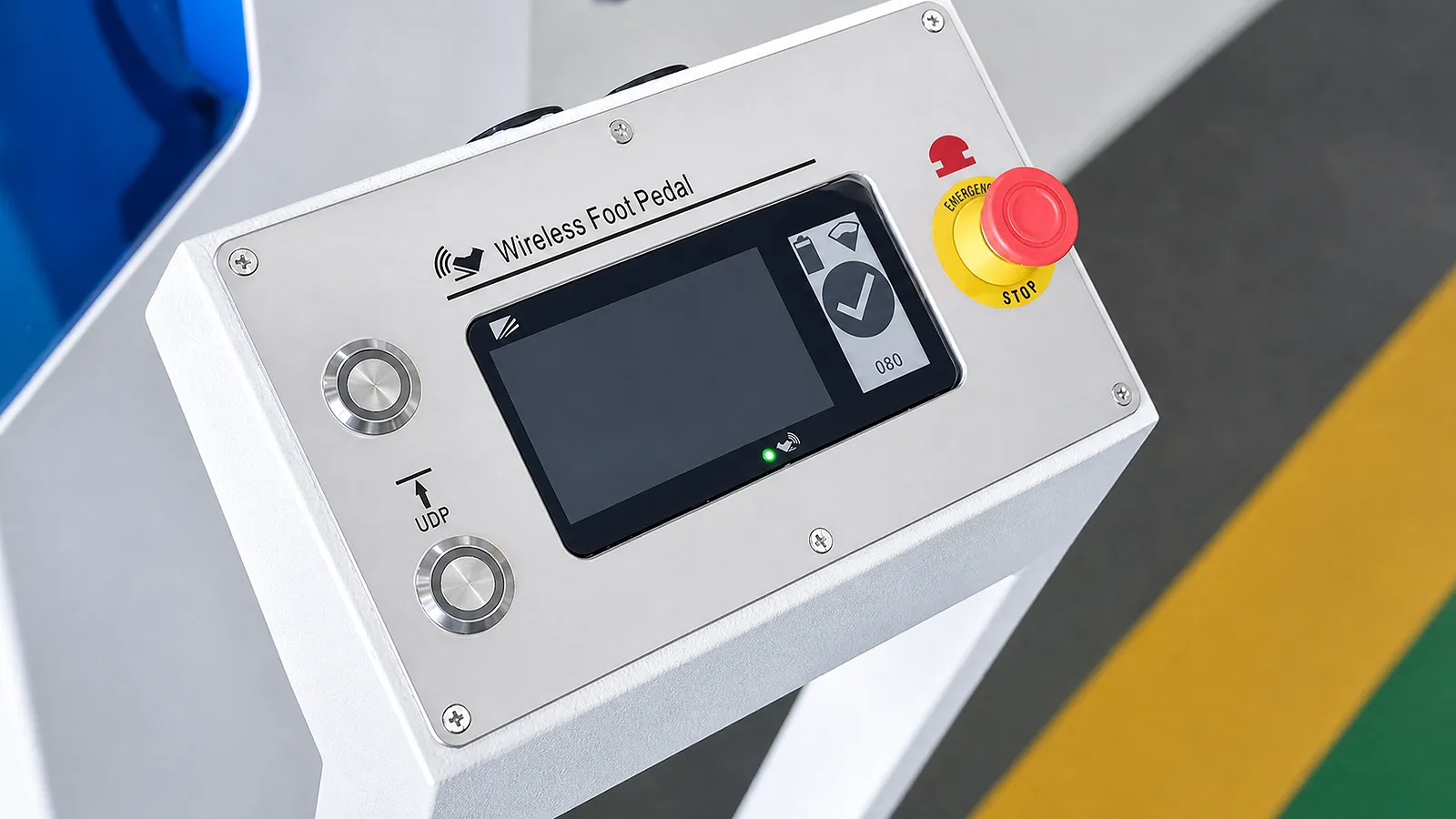
Best for
Press-brake operator work-area control
Compare
Pedal, WRM, MM, UM and display modules
Confirm
Platform, range, monitoring and site conditions
Information Needed
Share the machine and safety-controller model, its wiring diagram, the current pedal and the operator’s working area. These identify which interfaces the retrofit must support.
01 / WORKFLOW
Map where the operator stands, moves, handles sheet and needs control access.
02 / SYSTEM
List pedal, wireless/machine modules, display, sensors, charging and diagnostics.
03 / SAFETY
Check platform compatibility, interference, monitoring, safe-state behavior and tests.
Wireless-control components
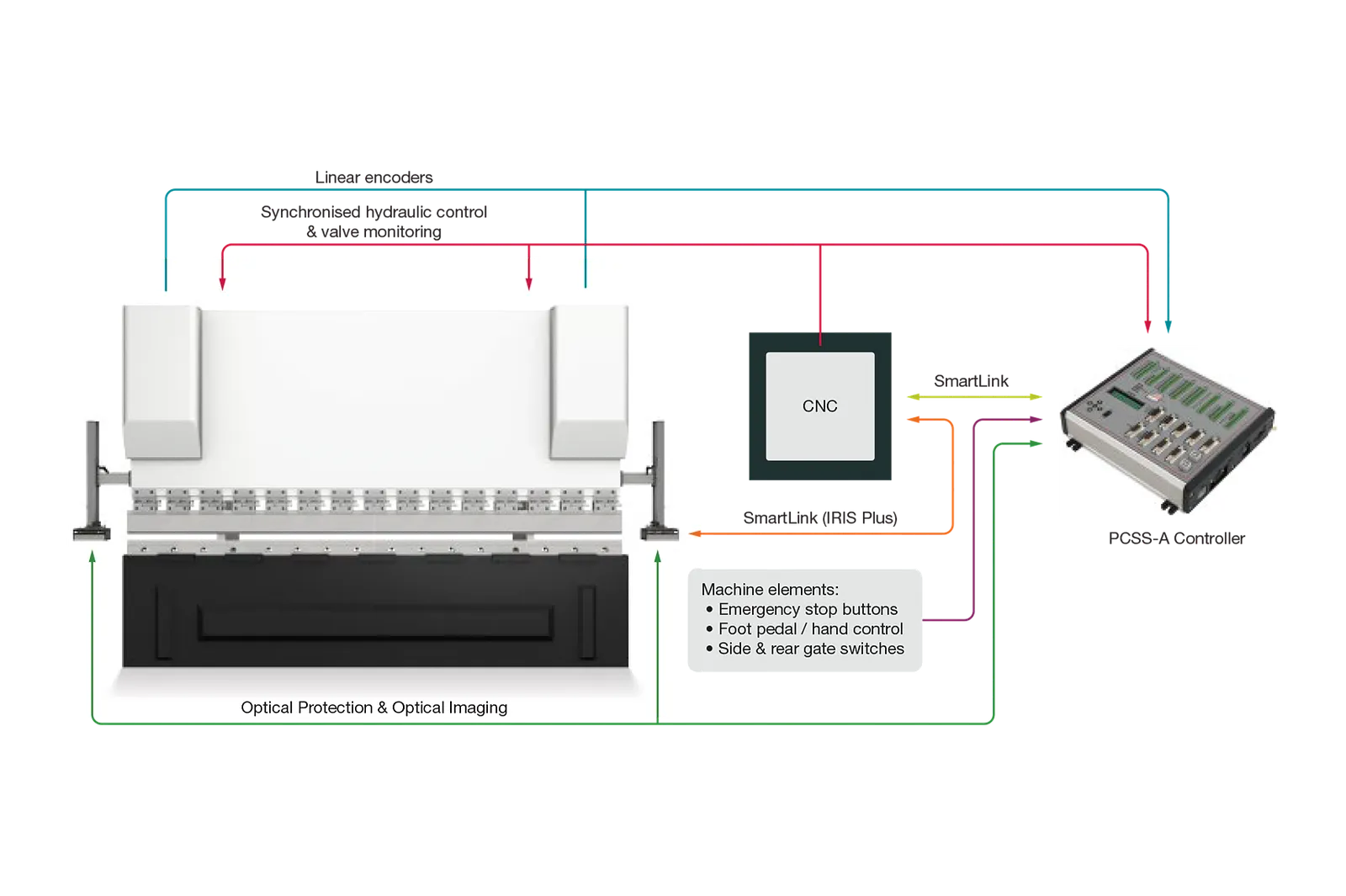
The Lazer Safe system pairs the pedal with a press-side module connected to the PCSS-A safety controller. Ultrasonic monitoring also tracks pedal position within the configured working area.
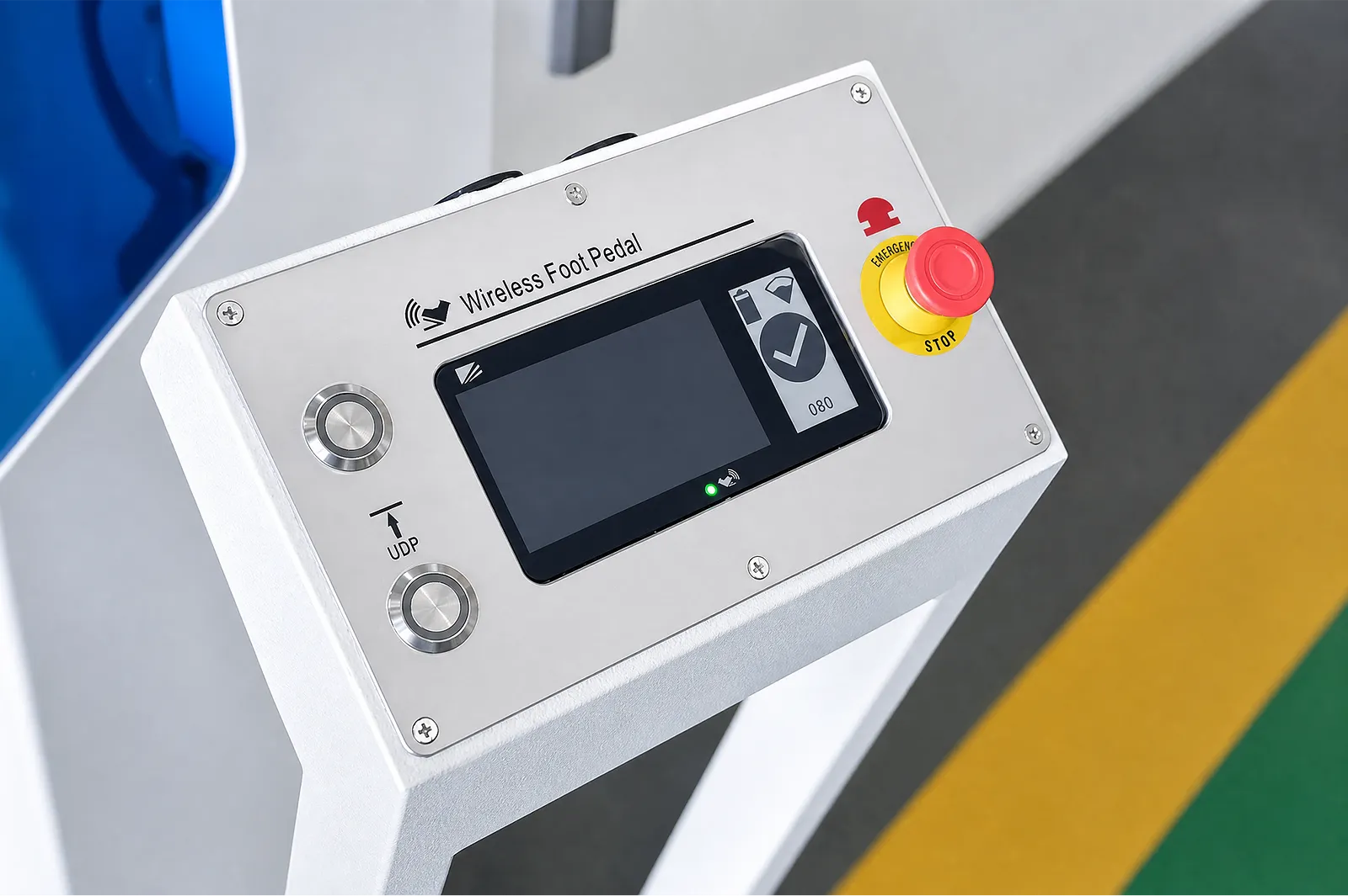
The wireless remote module (WRM) sends pedal commands to the machine module (MM), which connects to the PCSS-A controller. Match the control hardware and software revision to the machine wiring before specifying a retrofit.
Wireless foot pedal technical manual (PDF) →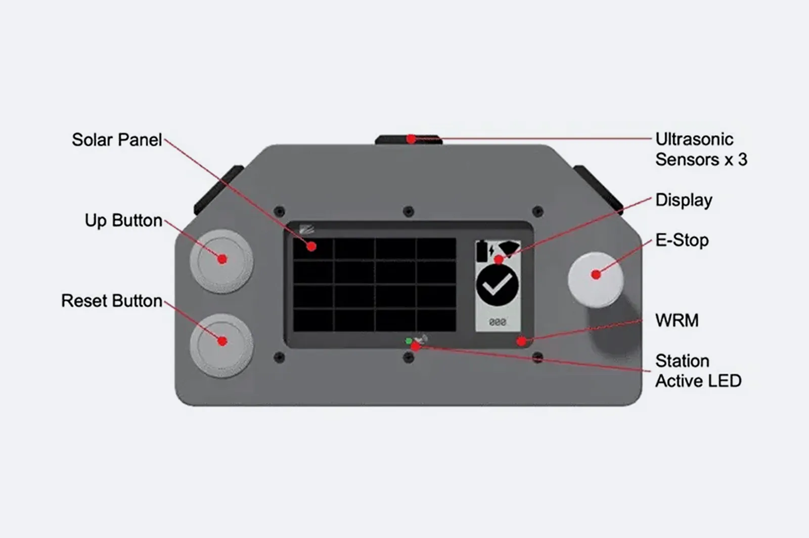
Review the complete foot-control system, including its machine interface and supplied components.
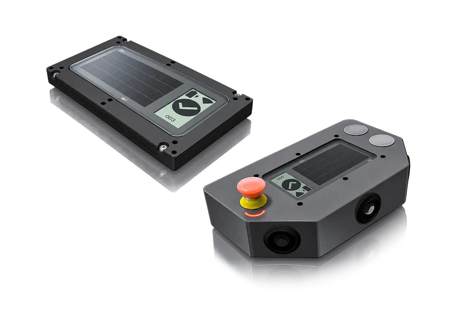
The WRM sits in the pedal station and transmits operator inputs to its paired MM. The machine-side receiver interfaces with the PCSS-A controller.
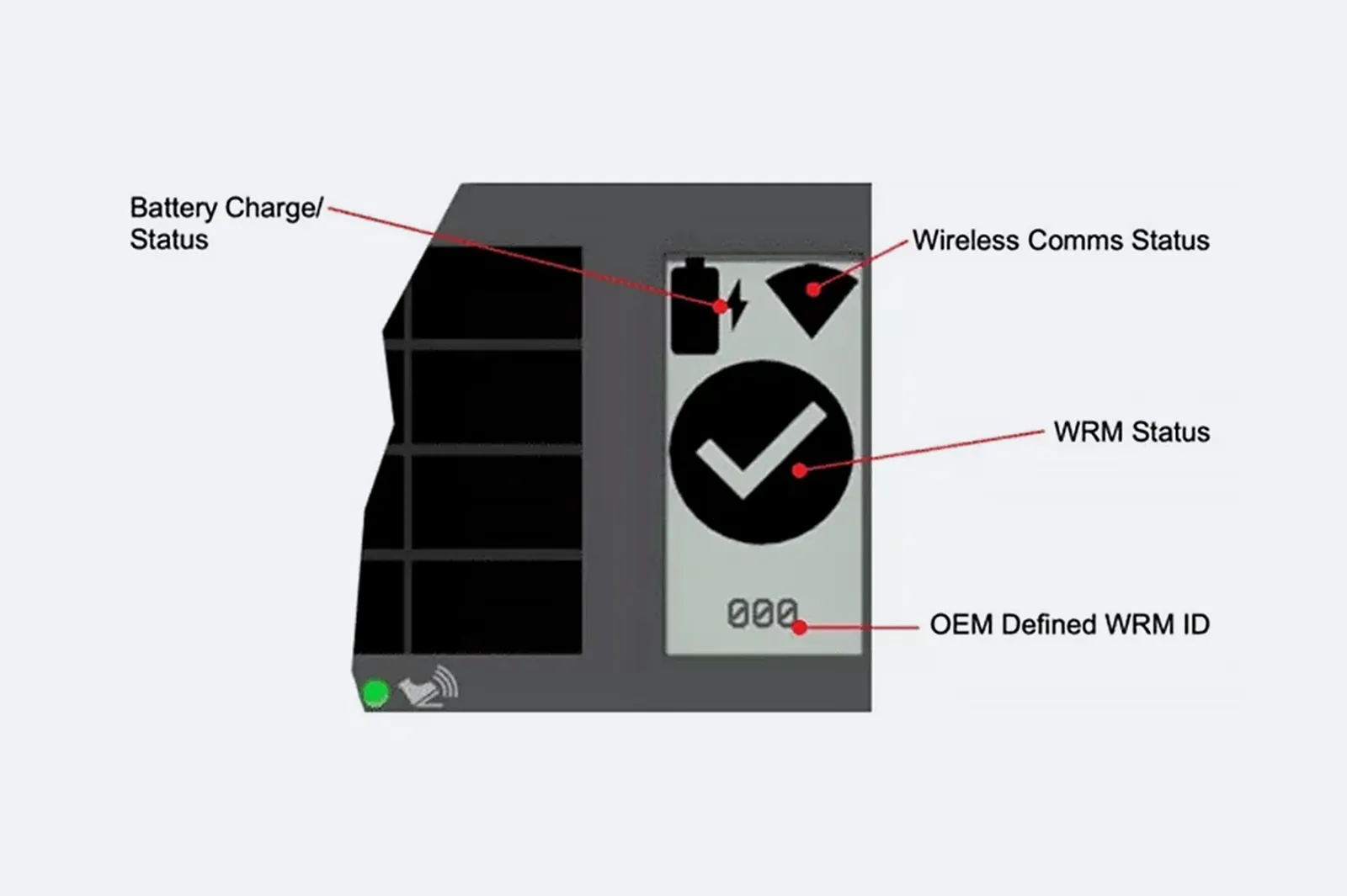
The pedal display identifies the paired station and shows battery and wireless status. Check that the operator can read the indication from the working position.
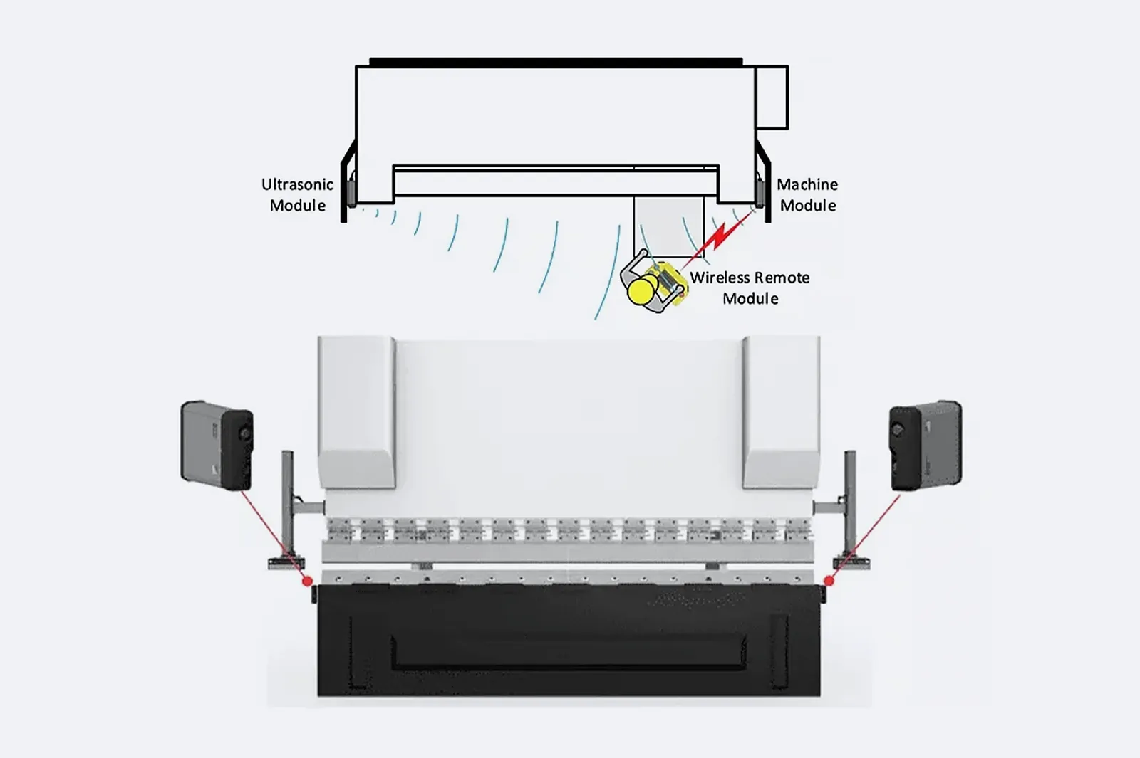
The press-side MM communicates with the WRM. The UM on the opposite side adds ultrasonic position sensing. Verify the monitoring zone and machine response during commissioning.
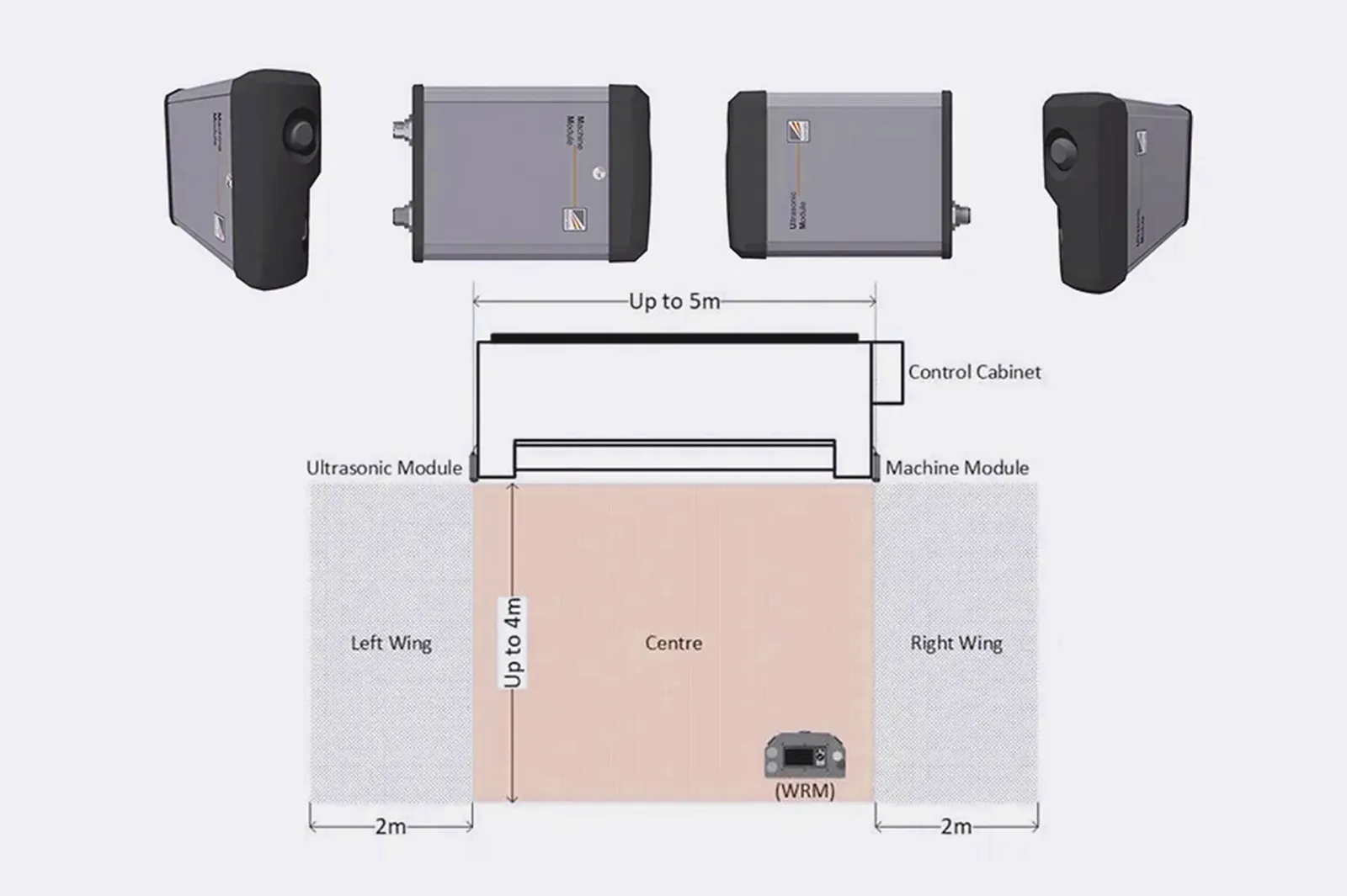
Confirm the sensors’ documented monitoring function and safe-state response for the work area.
Before You Order
For the quotation, identify the safety-controller revision, machine I/O, pedal modules and site layout. Agree on functional tests, pairing checks and validation of the installed monitoring zone.
Upgrade path
Identify the production problem, check compatibility, then agree installation and acceptance.
STEP 01
Record machine, controller, interfaces, photos, workflow and the production issue to solve.
STEP 02
Connect workpieces, process, operator tasks, output and site conditions to the upgrade.
STEP 03
Review mechanical, electrical, control, software, safety and service interfaces.
STEP 04
Define installation, tests, acceptance, documentation, training and support responsibilities.
Before You Contact ADH
Compatibility depends on control circuit, safety logic, radio environment, operator method and verified machine response.
Check machine/safety platform, communication modules, monitoring, site conditions and validation.
Send machine, controller, safety platform, work-area layout, workflow, photos and required functions.
Compare pedal circuit, safety contacts, receiver interface, radio conditions and validation.
Name pedal/receiver, control and safety integration, installation, tests, training and service terms.
Project enquiry
Tell us what you want to make or improve. Technical details and drawings can follow.
Contact ADH
Name, email and a short description are enough to begin.