Best for
Press-brake tool-area risk reduction
Press Brake Upgrade
Match detection, mounting, stopping and control interfaces to the tool area, material path and operator access. Validate the complete safety function on the selected machine.
Best for
Press-brake tool-area risk reduction
Compare
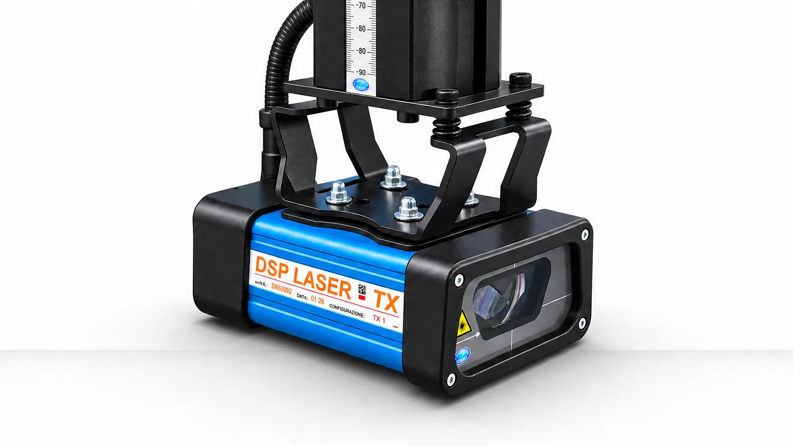
DSP, integrated optical protection and safety controls
Confirm
Machine interfaces, brackets, standards and validation
Information Needed
Describe the hazardous movement, access zone, material handling and operating mode the protection must address.
01 / RISK
Map the tool area, operator position, material path, bend sequence and intervention points.
02 / SYSTEM
Connect sensor field, stopping response, brackets and controller interfaces as one protective function.
03 / VERIFY
Confirm installation, tests, documents and applicable requirements with qualified specialists.
Safeguarding options
Select detection, stopping, mounting and control together, then validate the complete safety function.
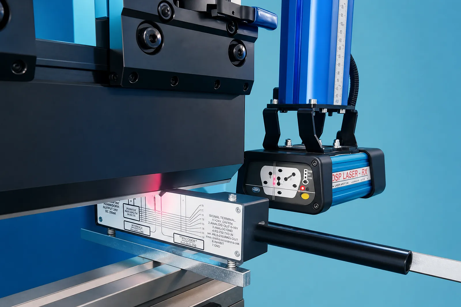
Check the DSP protective field, mounting and control interfaces against the machine’s risk assessment.
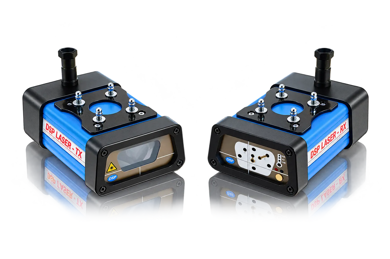
Define the protective equipment and its connections to the machine controls.
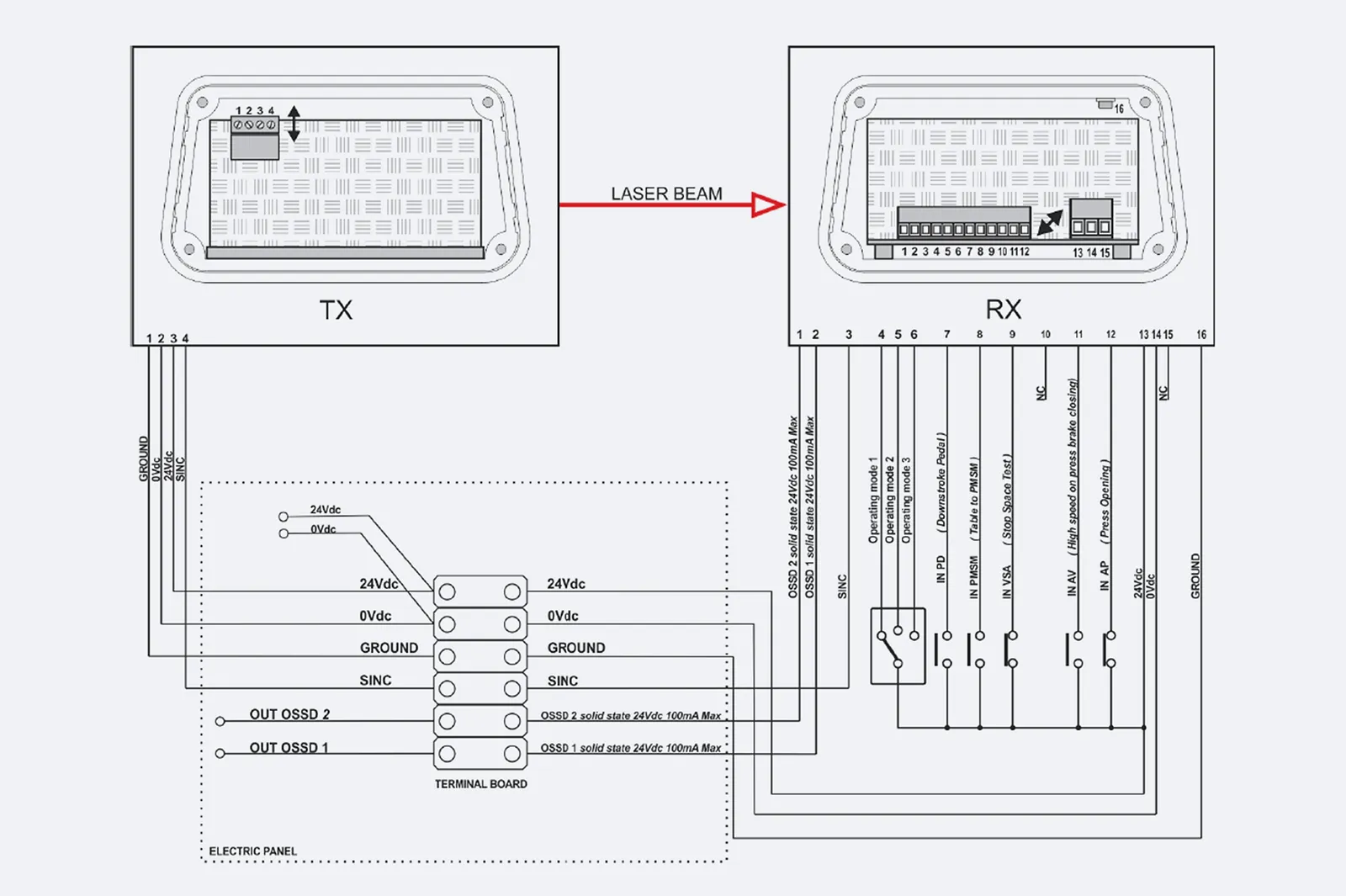
Document stopping functions, control interfaces and the required validation.
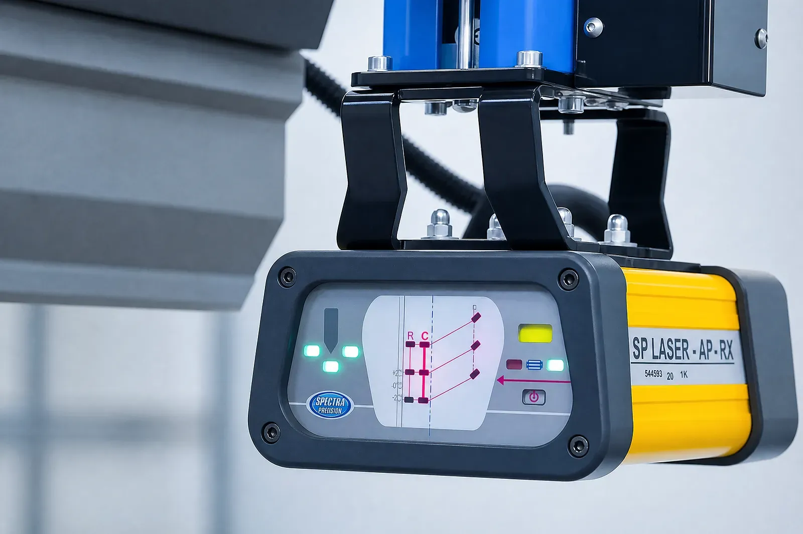
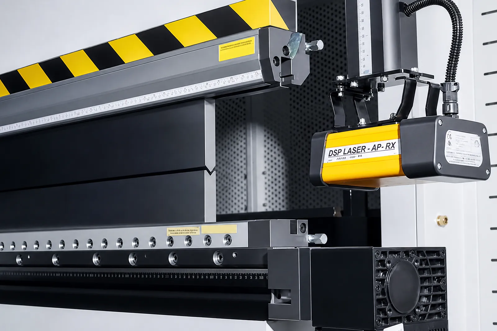
Confirm the MCS + DSP AP components, mounting arrangement and validation tests.
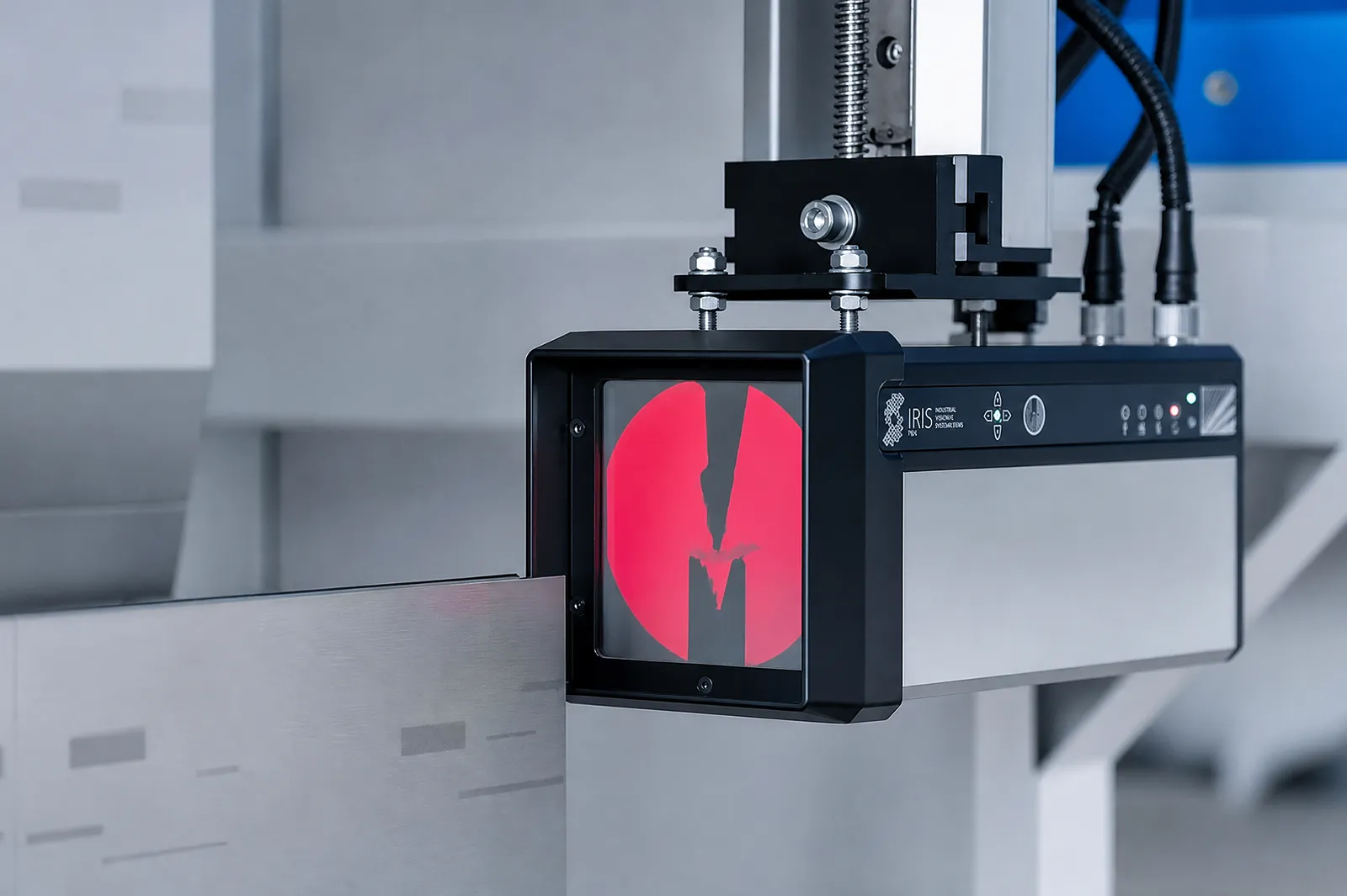
Review the system’s documented protective functions and compatibility with the machine.
Verify how speed monitoring and control contribute to the required safety function.
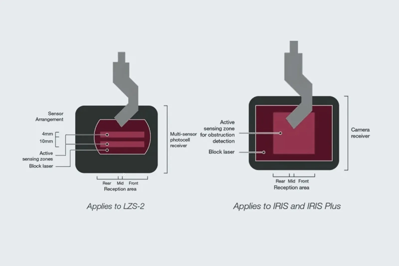
Confirm alignment functions, compatible tooling and the included hardware.
Confirm standards and verification documents for the final machine; this is an acceptance requirement, not a standalone option.
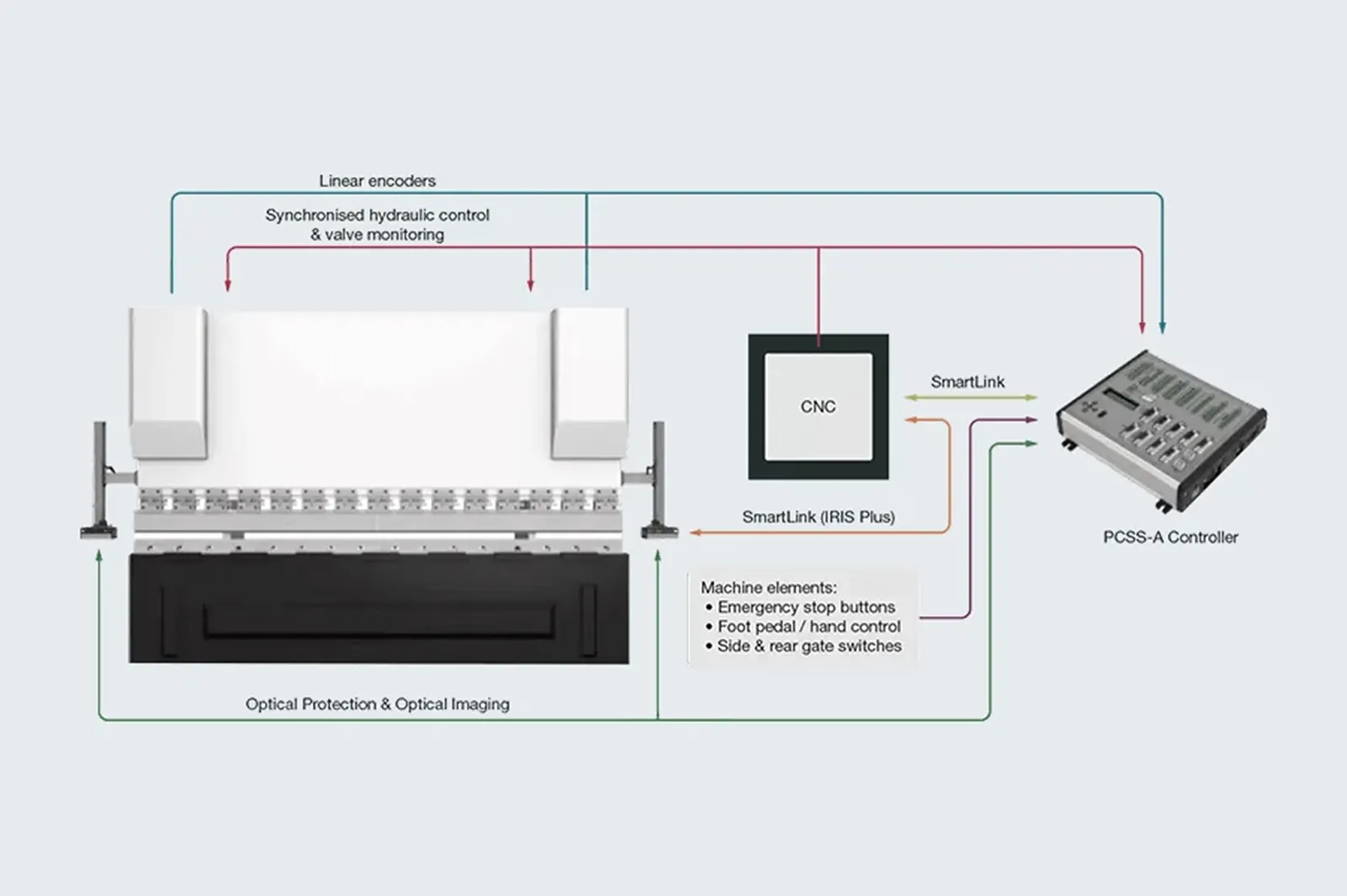
Check safety-control and stopping interfaces as part of the complete validated system.
Before You Order
Confirm the hazard zone, detection, stopping circuit, mounting, operating modes and validation records as one system.
Upgrade path
Identify the production problem, check compatibility, then agree installation and acceptance.
STEP 01
Record machine, controller, interfaces, photos, workflow and the production issue to solve.
STEP 02
Connect workpieces, process, operator tasks, output and site conditions to the upgrade.
STEP 03
Review mechanical, electrical, control, software, safety and service interfaces.
STEP 04
Define installation, tests, acceptance, documentation, training and support responsibilities.
Before You Contact ADH
Compatibility depends on machine motion, safety circuit, stop function, mounting and validated protective field.
Check machine control, stopping circuit, tool area, mounting, operating mode and validation requirements.
Send model, controller, safety circuit, tool-area photos, workpieces and operating method.
Evaluate stop category, mounting, protective field, machine motion and validation together.
Name sensors, controller, mounting, safety integration, validation, training and service terms.
Project enquiry
Tell us what you want to make or improve. Technical details and drawings can follow.
Contact ADH
Name, email and a short description are enough to begin.