
Best for
Reliable workpiece positioning at the backgauge
Press Brake Upgrade
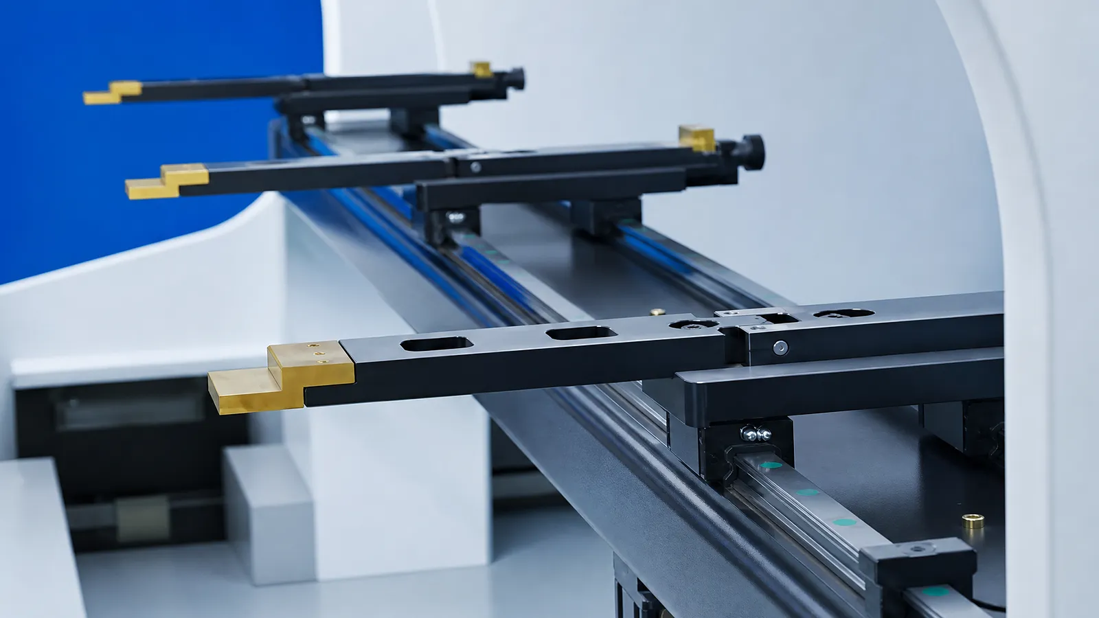
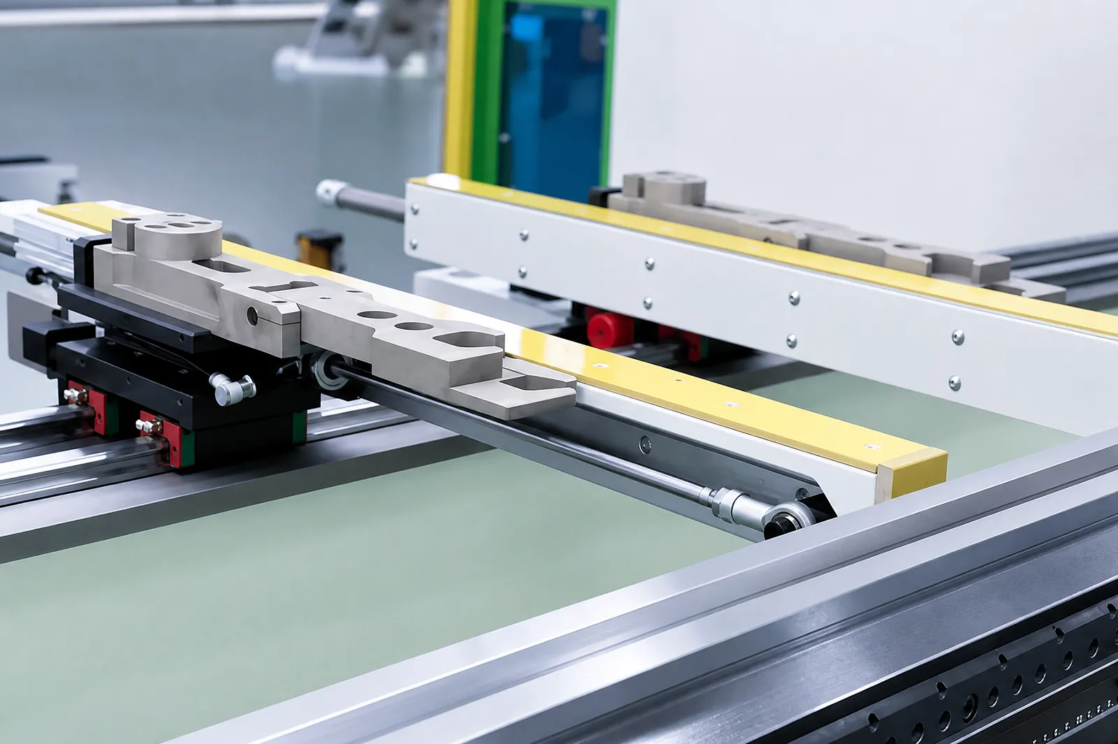
Finger geometry and adjustment determine where the workpiece locates. Match contact surfaces, X/R/Z movement, tooling clearance and bend sequence.
Best for
Reliable workpiece positioning at the backgauge
Compare
Standard, adjustable and multi-point fingers
Confirm
Part contact, axes, travel and collision clearance
Information Needed
Describe flange geometry, openings, edge condition, bend sequence and positioning issue.
01 / CONTACT
Use the part edge, openings and bend sequence to define where the finger locates the workpiece.
02 / ADJUST
Use micro-adjustment, dual stops or independent positions only when the part requires them.
03 / CLEARANCE
Check finger mount, X/R/Z travel, tooling, part rotation and collision envelope.
Stop-finger options
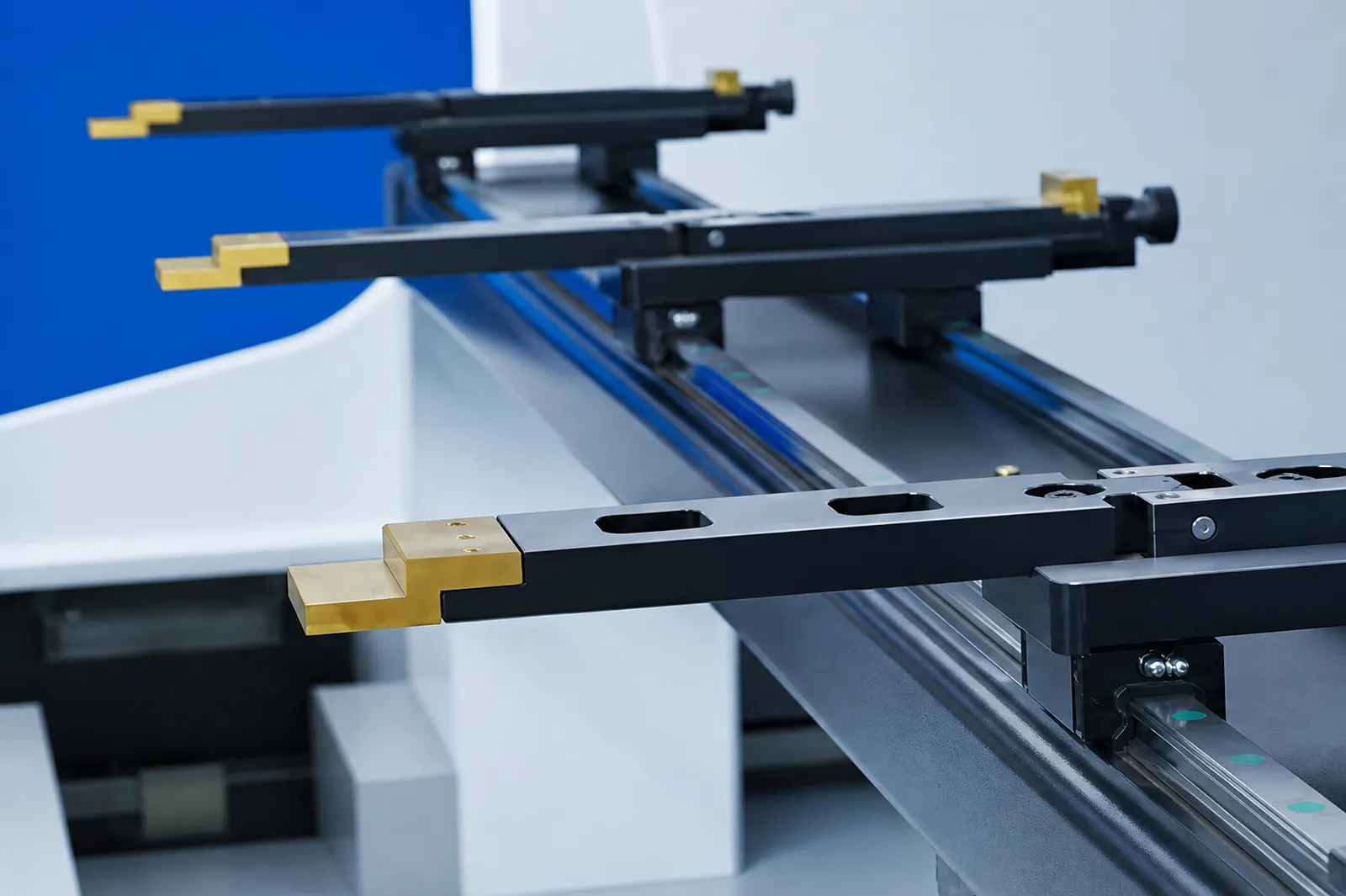
Match the contact geometry and mounting to the part and backgauge. Check travel and clearance.
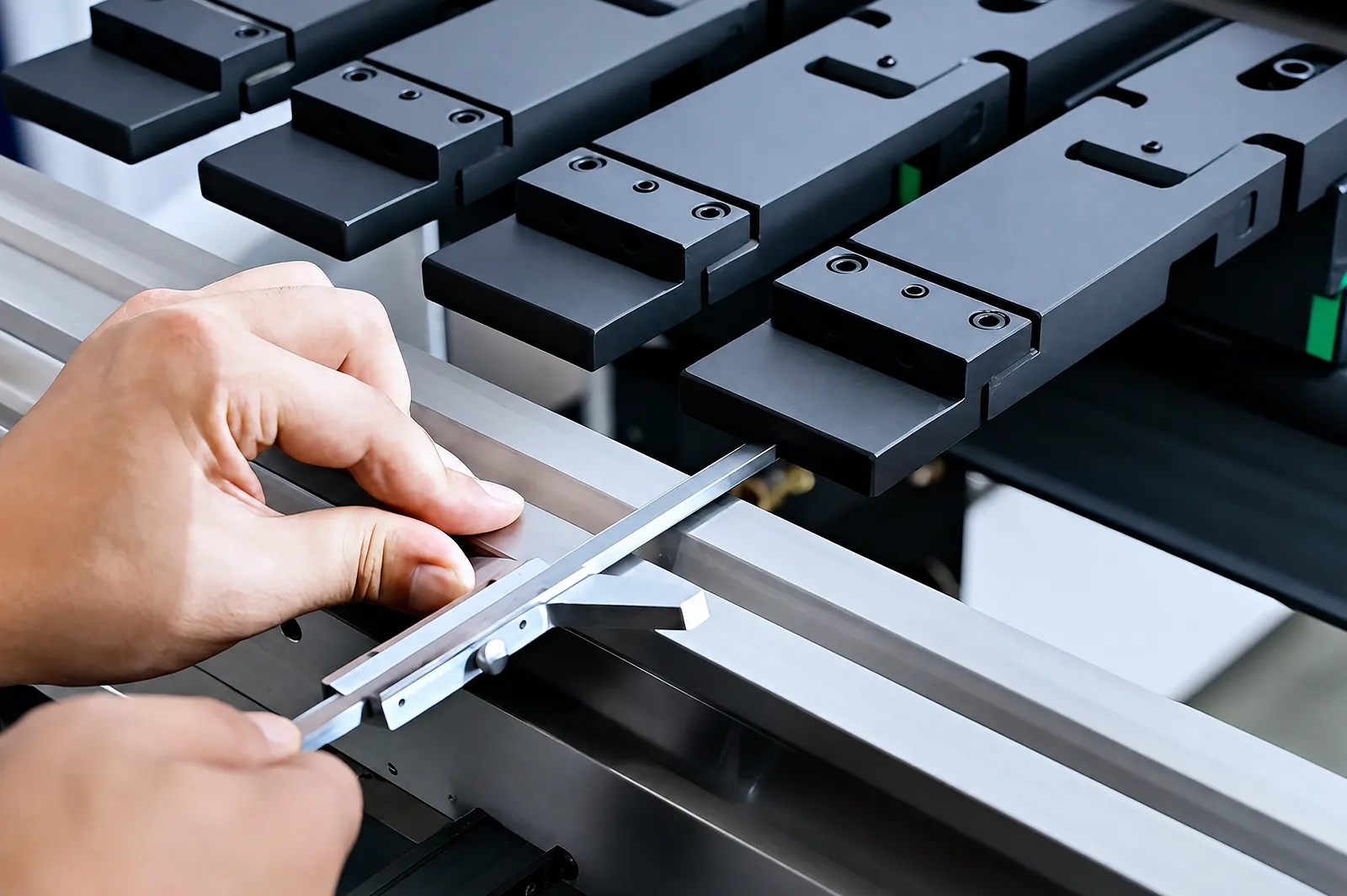
Choose the adjustment range for the positioning task, then check mounting and clearance.
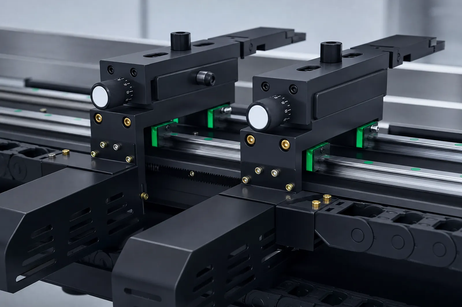
Use multiple contact points where the part requires them. Check available axes and collision clearance.
Before You Order
Backgauge fingers locate the part; sheet supports carry or follow it. Specify the two functions separately.
Upgrade path
Identify the production problem, check compatibility, then agree installation and acceptance.
STEP 01
Record machine, controller, interfaces, photos, workflow and the production issue to solve.
STEP 02
Connect workpieces, process, operator tasks, output and site conditions to the upgrade.
STEP 03
Review mechanical, electrical, control, software, safety and service interfaces.
STEP 04
Define installation, tests, acceptance, documentation, training and support responsibilities.
Before You Contact ADH
Compatibility depends on beam, axes, mounting, contact surface and positioning task.
Check beam, mount, axes, travel, workpiece contact and collision envelope.
Send machine/backgauge model, mount photos, drawings, flange geometry, bend sequence and positioning issue.
Compare beam, carriage, finger interface, travel, part geometry, collision zones and positioning test.
Name finger type, hardware, mounting, axis implications, installation, tests and service terms.
Project enquiry
Tell us what you want to make or improve. Technical details and drawings can follow.
Contact ADH
Name, email and a short description are enough to begin.