
Best for
Managing angle variation during bending
Press Brake Upgrade
IRIS Plus and LaserCheck connect measurement to correction. Select from material variation, tooling, bend geometry, sensor access and controller feedback.
Best for
Managing angle variation during bending
Compare
IRIS Plus and LaserCheck systems
Confirm
Tooling, geometry, feedback and closed-loop method
Information Needed
Describe material, thickness, grain, tooling, bend geometry, springback, tolerance and observed angle variation.
01 / VARIATION
Record what changes the angle and when it appears.
02 / ACCESS
List sensor view, flange geometry, tool restrictions and machine interfaces.
03 / LOOP
Define result transfer, correction method and finished-angle check.
Measurement options
Compare where the sensor sees the bend, when the controller receives an angle and how the result is checked on the finished part.
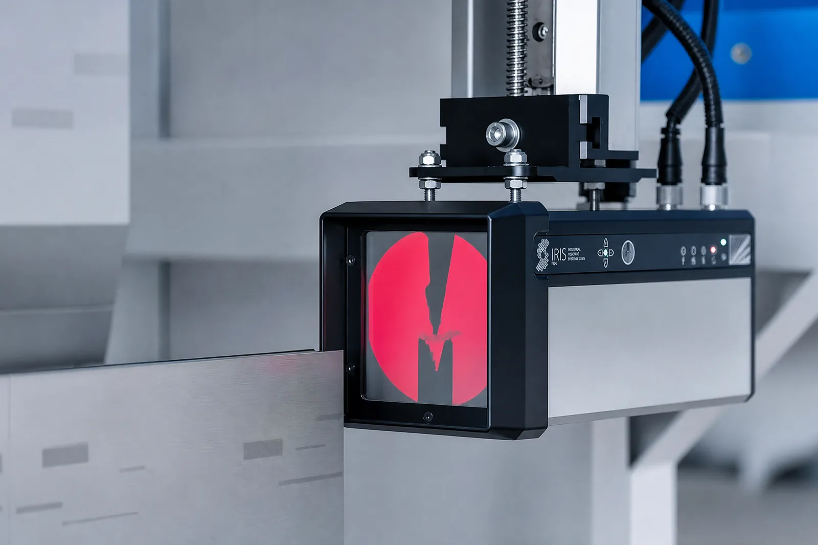
IRIS Plus uses optical imaging near the upper tooling. With the supported CNC interface, the image-processing system can track the bend and measure the final angle. Check the tool profile, line of sight and the control functions supplied.
Download technical PDF →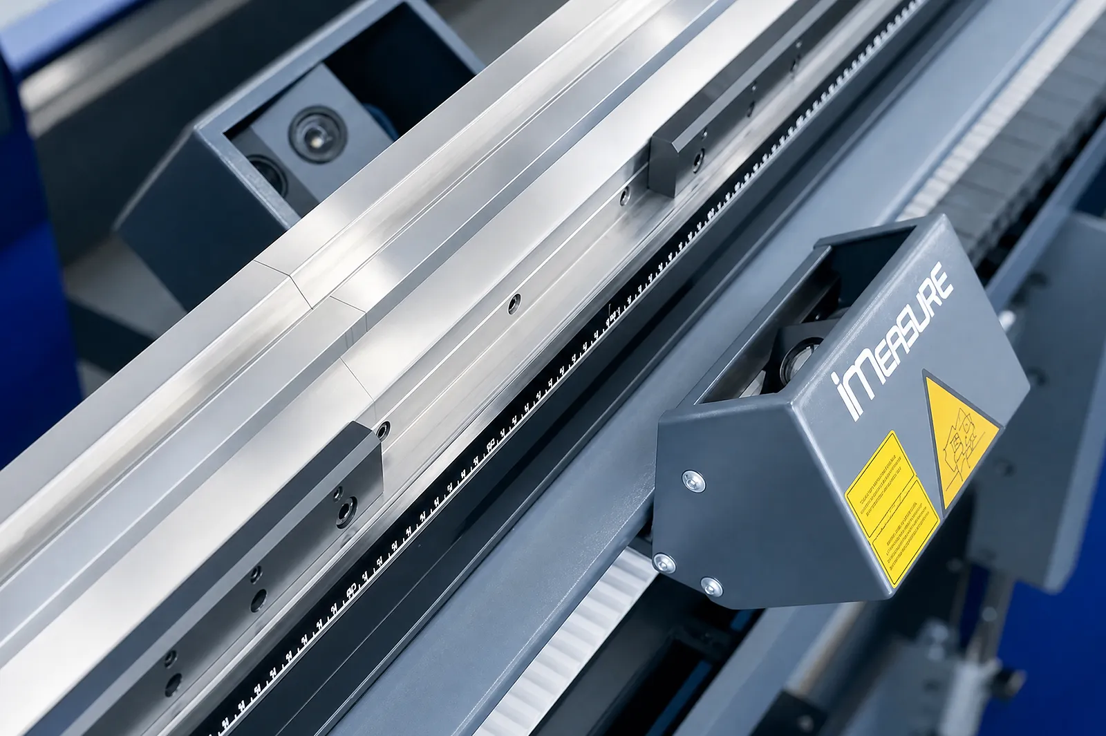
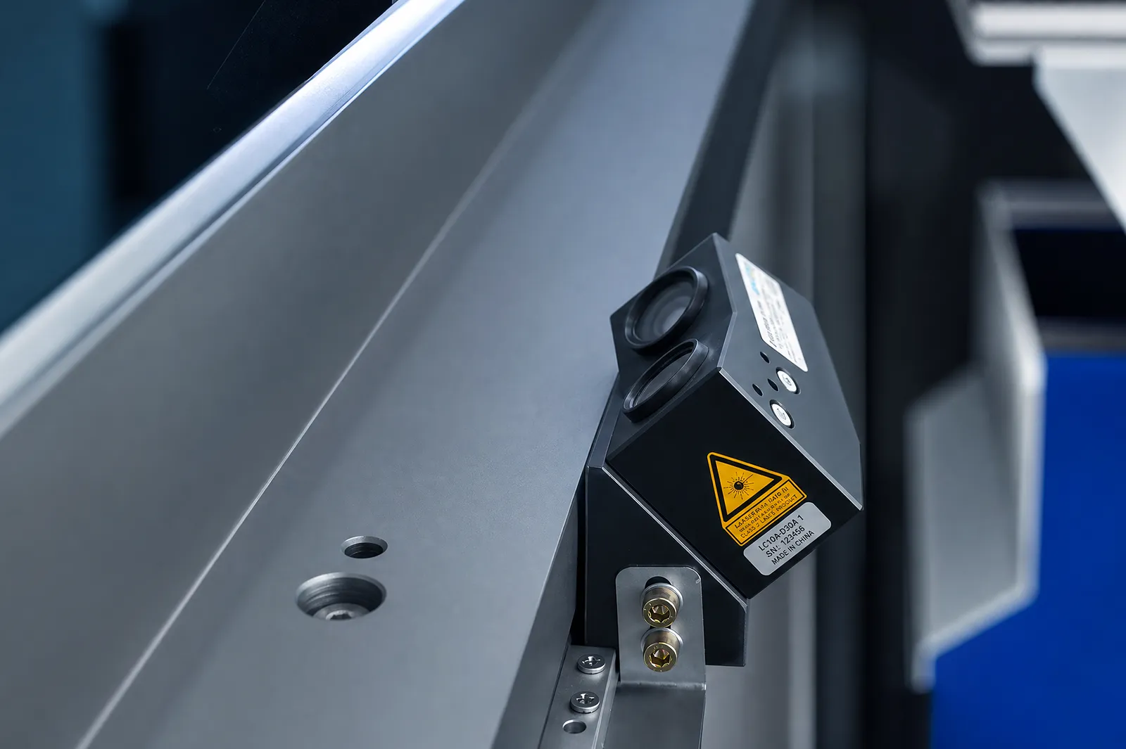
LaserCheck uses laser triangulation from sensors on opposite sides of the sheet near the die. The controller uses both sheet-surface measurements to calculate the angle. Confirm sensor positions, die clearance and the selected correction interface.
Download technical PDF →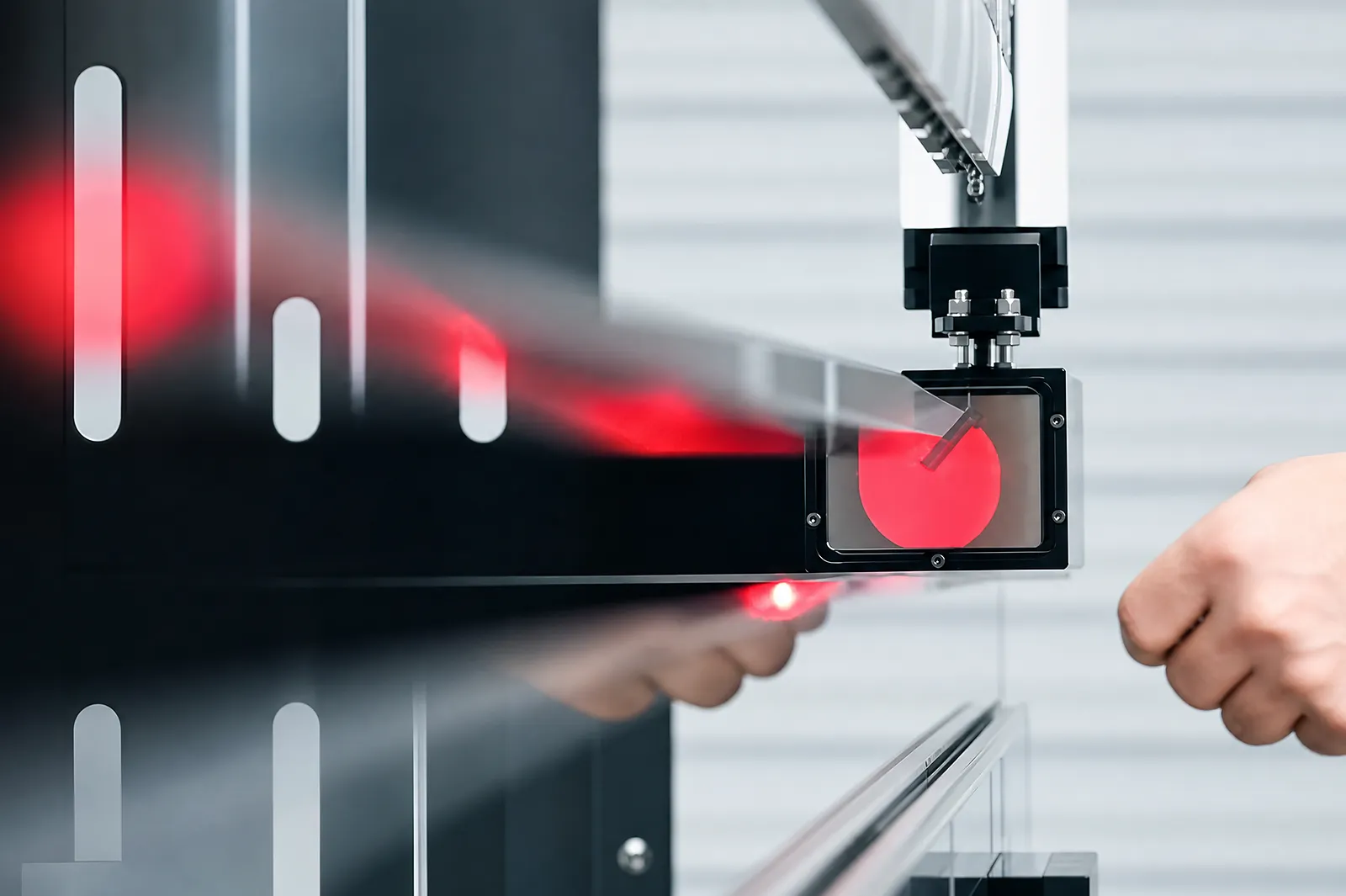
Use the intended punch, die, material and flange geometry. Verify sensor alignment, compare the reported angle with an independent measurement after unloading, and record any correction against the agreed tolerance.
Before You Order
Measurement improves the process only when the result drives a defined correction and acceptance check.
Upgrade path
Identify the production problem, check compatibility, then agree installation and acceptance.
STEP 01
Record machine, controller, interfaces, photos, workflow and the production issue to solve.
STEP 02
Connect workpieces, process, operator tasks, output and site conditions to the upgrade.
STEP 03
Review mechanical, electrical, control, software, safety and service interfaces.
STEP 04
Define installation, tests, acceptance, documentation, training and support responsibilities.
Before You Contact ADH
Compatibility depends on machine, controller, tooling, part geometry, material and application.
Check tooling, part access, controller interface, correction workflow and measurement range.
Send machine, controller, tooling, materials, representative parts, target angles and current variation.
Compare controller, tooling, sensor position, part access, bend sequence and accuracy check.
Specify the measurement system, hardware, software, controller integration, calibration, tests and training.
Project enquiry
Tell us what you want to make or improve. Technical details and drawings can follow.
Contact ADH
Name, email and a short description are enough to begin.