
Best for
Existing or planned press-brake positioning requirements
Press Brake Upgrade
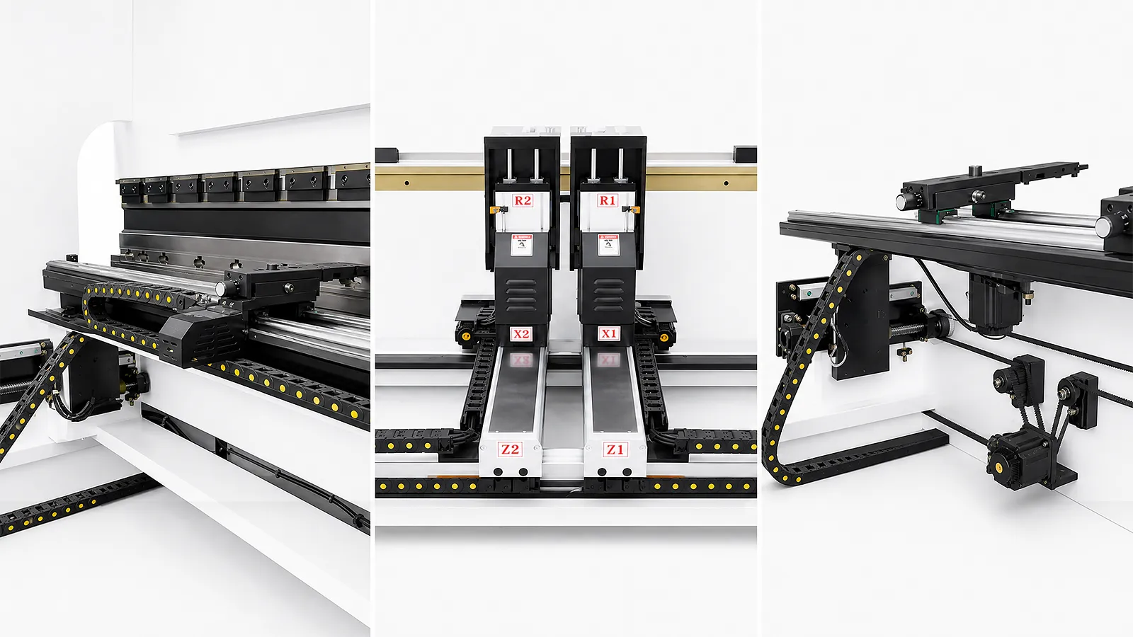
The bend sequence determines whether 2, 4 or 6 axes are useful. Check the existing controller, travel, structure and guarding before a modification is specified.
Best for
Existing or planned press-brake positioning requirements
Compare
2-axis, 4-axis and 6-axis backgauges
Confirm
Controller, travel, space, wiring and verification
Information Needed
Start with the bend sequence and current machine; the axis layout follows the required movements and available interfaces.
01 / PART
Share the bend sequence, flange geometry, part width and the movements needed between bends.
02 / AXES
Assign X, R, Z1/Z2 or independent axes only when they solve a defined positioning need.
03 / RETROFIT
List controller, beam and guide space, motors, feedback, wiring and guarding before modification.
Backgauge options
More axes help only when they remove a real positioning limitation.
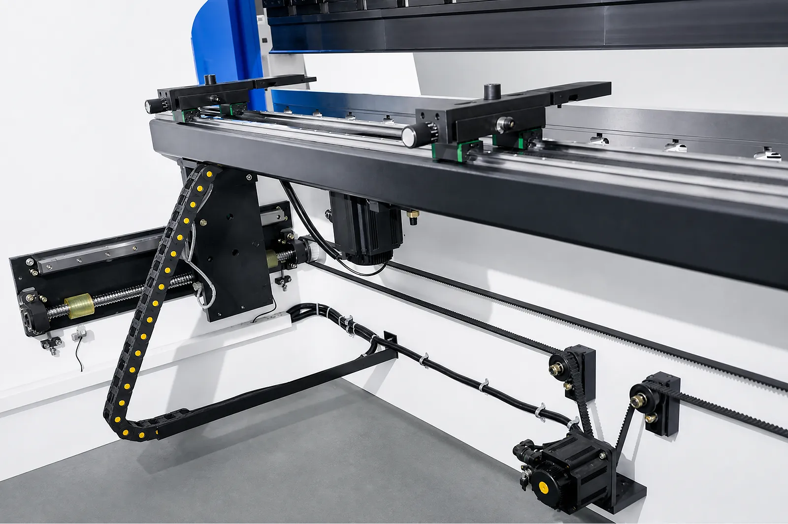
Use X and R for depth and height positioning on the defined part family; confirm travel and controller interfaces.
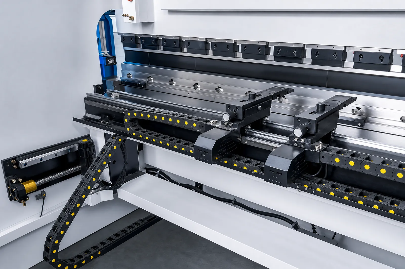
Add independent Z1/Z2 movement when the part or tooling requires lateral positioning.
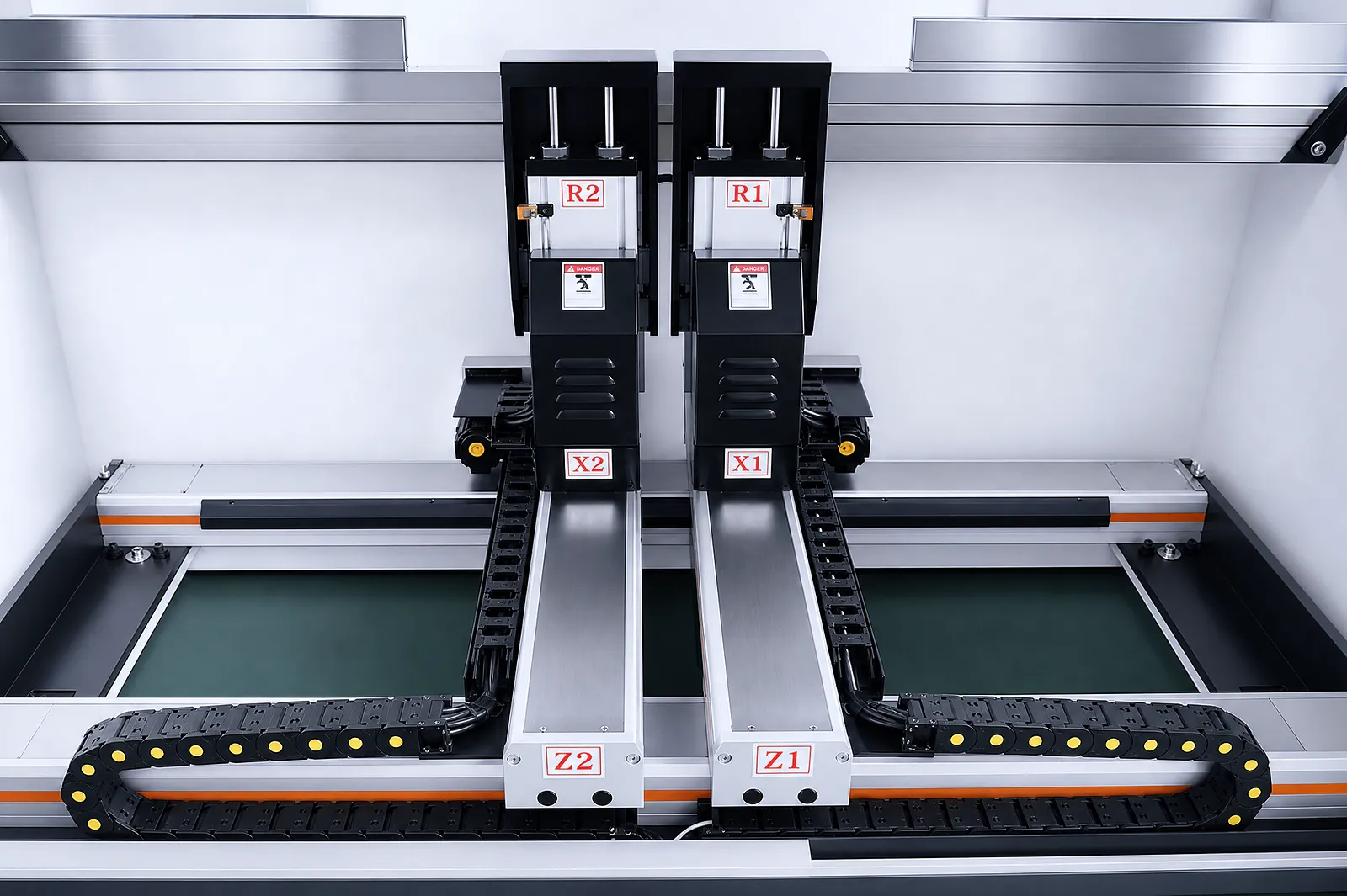
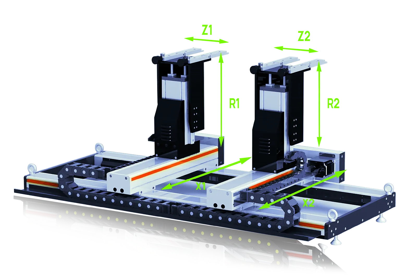
Use independent X1/X2, R1/R2, Z1/Z2 movements for asymmetric or complex positioning when the machine can support them.
Before You Order
Axis count, mechanics, drives, feedback and control must support the same positioning method.
Modification process
Define the task, check interfaces, agree hardware and installation, then test the completed positioning method.
STEP 01
Record model, controller, current backgauge, photos, dimensions and observed limitations.
STEP 02
Map the workpiece, bend sequence, positioning axes, travel and load requirements.
STEP 03
Define installation, tests, acceptance, training, documentation and service responsibilities.
STEP 04
Run representative positioning tasks and verify travel, clearances, control functions and the agreed acceptance criteria.
Before You Contact ADH
Compatibility depends on the existing machine and the required positioning task.
Check frame, controller, space, drive, feedback, wiring and guarding before committing to a modification.
Start with the part and bend sequence. Add axes only when they solve a defined depth, height or lateral positioning requirement.
Send model, controller, existing backgauge, photos, drawings, part geometry, bend sequence and travel.
Name axis layout, hardware, interfaces, installation, tests, acceptance, training and service terms.
Project enquiry
Tell us what you want to make or improve. Technical details and drawings can follow.
Contact ADH
Name, email and a short description are enough to begin.