
01
Sheet and load
Provide sheet size, weight, flatness, surface condition and loading/removal access.
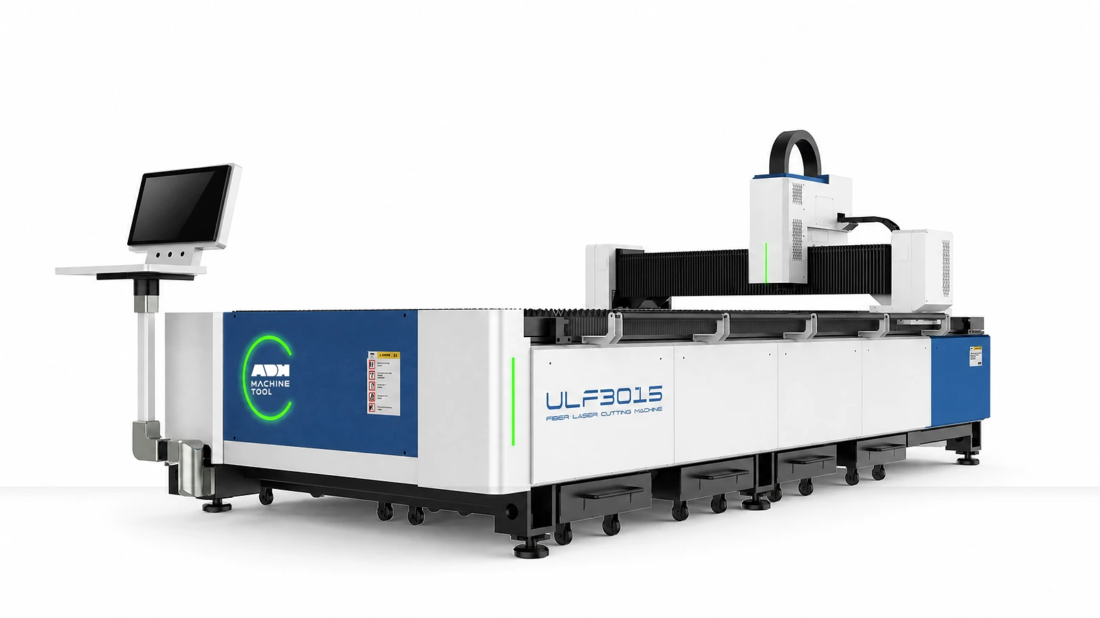
Fiber Laser Cutting | ULF Series
A direct-access flat-sheet laser platform for manufacturers that need a defined working format, source package and loading route.
Technical specifications
Select one G or E model. Maximum speed depends on the drive package. Acceleration is single-axis for ULF-G and coupled-axis for ULF-E. ULF-G table load assumes a uniformly distributed, stably placed load.
| Model | Family | Laser Power | Processing Area | Z Travel | Beam Clearance | Positioning Accuracy (unit as shown) | Repeatability (unit as shown) | Max Coupled Speed | Max Acceleration | Table Load | Overall Dimensions | Rated Voltage | Frequency |
|---|---|---|---|---|---|---|---|---|---|---|---|---|---|
| Unit | kW | mm | mm | mm | m/min | g | kg | mm | V | Hz | |||
| 3015G | ULF-G | 1.5–6 | 3100×1530 | 150 | 100 | ≤±0.03mm/m | ≤±0.02mm/m | 90 (Inovance/BOCHU S9); 70 (Delta) | 1.4 (single axis) | 900 | 4700×2345×1850 | 380 | 50 |
| 4015G | ULF-G | 1.5–6 | 4100×1530 | 150 | 100 | ≤±0.03mm/m | ≤±0.02mm/m | 90 (Inovance/BOCHU S9); 70 (Delta) | 1.4 (single axis) | 1200 | 6000×2345×1850 | 380 | 50 |
| 6015G | ULF-G | 1.5–6 | 6100×1530 | 150 | 100 | ≤±0.03mm/m | ≤±0.02mm/m | 90 (Inovance/BOCHU S9); 70 (Delta) | 1.4 (single axis) | 1800 | 8300×2345×1850 | 380 | 50 |
| 4020G | ULF-G | 1.5–6 | 4100×2050 | 150 | 100 | ≤±0.03mm/m | ≤±0.02mm/m | 90 (Inovance/BOCHU S9); 70 (Delta) | 1.4 (single axis) | 1600 | 6000×2916×1850 | 380 | 50 |
| 6020G | ULF-G | 1.5–6 | 6100×2050 | 150 | 100 | ≤±0.03mm/m | ≤±0.02mm/m | 90 (Inovance/BOCHU S9); 70 (Delta) | 1.4 (single axis) | 2400 | 8300×2916×1850 | 380 | 50 |
| 3015E | ULF-E | 1.5–12 | 3100×1530 | 150 | 110/210 | ≤±0.03mm | ≤±0.02mm | 140 (Inovance/BOCHU S9); 100 (Delta) | 1.7 (coupled axes) | 1100 | 4700×2345×1950 | 380 | 50 |
| 4015E | ULF-E | 1.5–12 | 4100×1530 | 150 | 110/210 | ≤±0.03mm | ≤±0.02mm | 140 (Inovance/BOCHU S9); 100 (Delta) | 1.7 (coupled axes) | 1500 | 6000×2345×1950 | 380 | 50 |
| 6015E | ULF-E | 1.5–12 | 6100×1530 | 150 | 110/210 | ≤±0.03mm | ≤±0.02mm | 140 (Inovance/BOCHU S9); 100 (Delta) | 1.7 (coupled axes) | 2200 | 8300×2345×1950 | 380 | 50 |
| 4022E | ULF-E | 1.5–12 | 4100×2200 | 150 | 110/210 | ≤±0.03mm | ≤±0.02mm | 140 (Inovance/BOCHU S9); 100 (Delta) | 1.7 (coupled axes) | 2000 | 6000×3250×1950 | 380 | 50 |
| 6022E | ULF-E | 1.5–12 | 6100×2200 | 150 | 110/210 | ≤±0.03mm | ≤±0.02mm | 140 (Inovance/BOCHU S9); 100 (Delta) | 1.7 (coupled axes) | 3000 | 8300×3250×1950 | 380 | 50 |
| 6026E | ULF-E | 6–60 | 6100×2600 | 250 | 190 | ≤±0.03mm | ≤±0.02mm | 140 | 1.7 (coupled axes) | 3900 | 8700×3800×2050 | 380 | 50 |
| 8026E | ULF-E | 6–60 | 8000×2600 | 250 | 190 | ≤±0.04mm | ≤±0.02mm | 140 | 1.7 (coupled axes) | 5200 | 11000×3800×2050 | 380 | 50 |
| 13026E | ULF-E | 6–60 | 13000×2600 | 250 | 190 | ≤±0.07mm | ≤±0.03mm | 140 | 1.7 (coupled axes) | 14000 | 16300×3750×2450 | 380 | 50 |
| 13032E | ULF-E | 6–60 | 13000×3200 | 200 | 160 | ≤±0.07mm | ≤±0.03mm | 140 | 1.4 (coupled axes) | 18000 | 16500×4350×2450 | 380 | 50 |
| 26026E | ULF-E | 6–60 | 26000×2600 | 250 | 190 | ≤±0.07mm/10m | ≤±0.05mm | 140 | 1.7 (coupled axes) | 28000 | 31000×3750×2450 | 380 | 50 |
| 26032E | ULF-E | 6–60 | 26000×3200 | 200 | 160 | ≤±0.07mm/10m | ≤±0.05mm | 140 | 1.4 (coupled axes) | 36000 | 31500×4350×2450 | 380 | 50 |
Sheet-cutting inputs
For large-format ULF work, compare maximum sheet size and distributed table load with the loading route, lift capacity and extraction zones. Include the time needed to remove parts and the remaining skeleton before loading the next sheet.
01
Provide sheet size, weight, flatness, surface condition and loading/removal access.
02
Confirm material, thickness, gas, edge criteria and the representative cutting sample.
03
Define part mix, nesting, remnant handling and operating window.
04
Confirm power, cooling, extraction, software and any data interface.
Machine in operation
Watch the ULF cutting sequence, then compare its table, motion, process and control systems below.
Watch on YouTube (opens in a new tab)Product systems
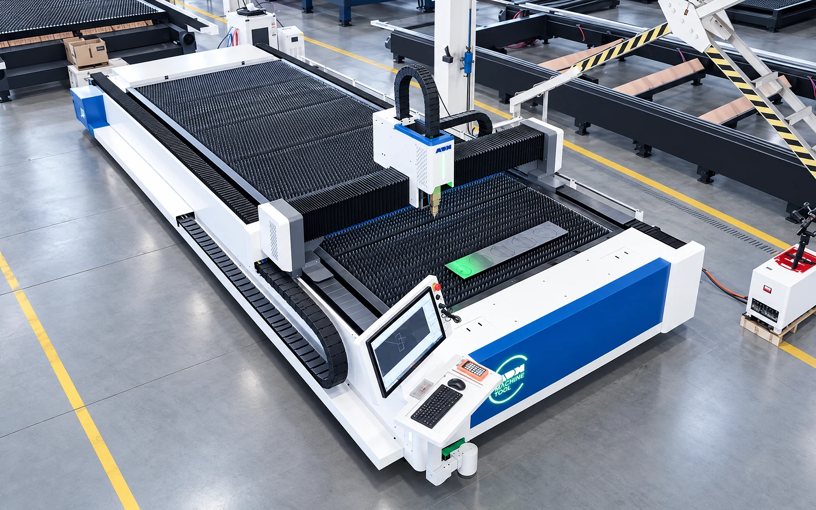
ULF brings loading, cutting and part removal to one worktable. Match the working format, moving head, cutting package and material-handling route to your sheet work.
01
Loading, cutting and part removal share a single table. The sheet rests on its supports while the cutting head follows the programmed path.
Review sheet weight, loading access, finished-part removal and remnants. This workflow should be assessed against the intended job mix and handling method.
02
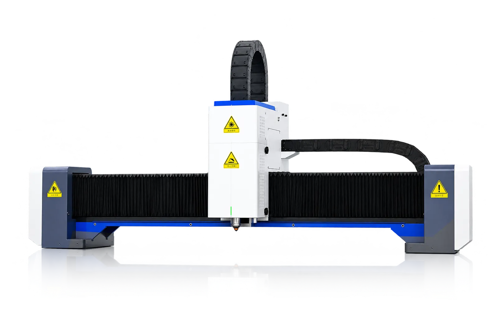
The beam and drives position the cutting head over the worktable. Transmission protection and lubrication support the motion system through routine operation.
Read travel, speed, acceleration and positioning from the exact G or E model. A value from one format should not be generalized to another.
Laser source
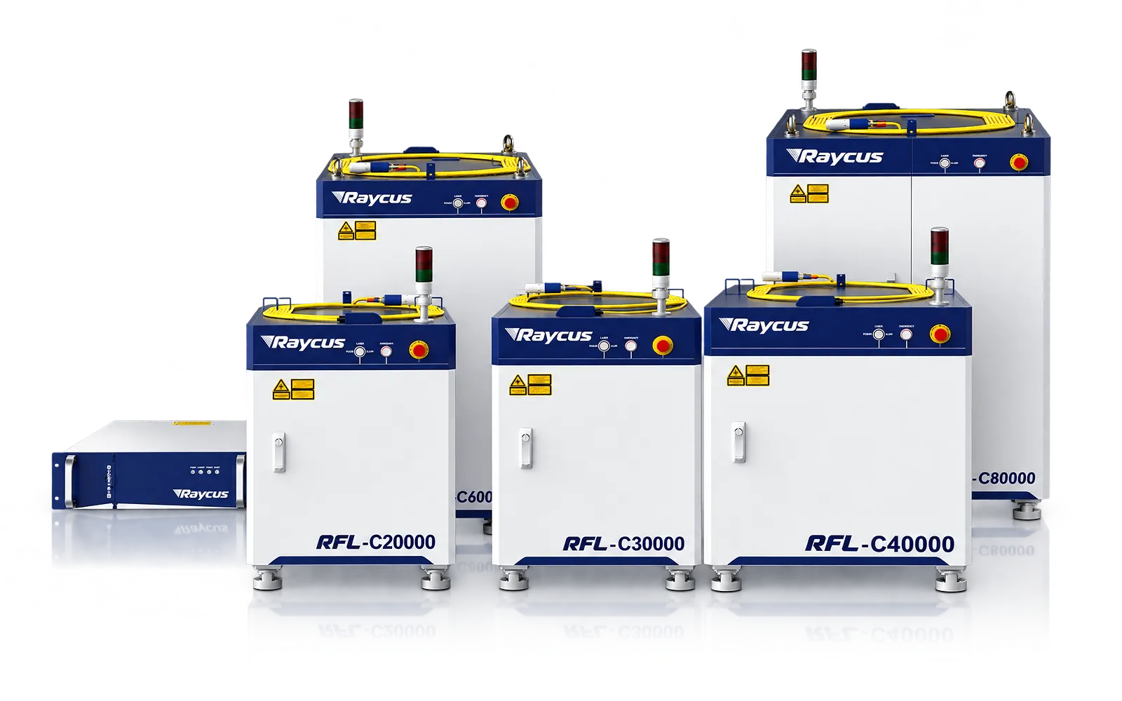
The laser source supplies the cutting process for the selected material and thickness.
Review delivered power with representative parts; capacity depends on the complete setup.
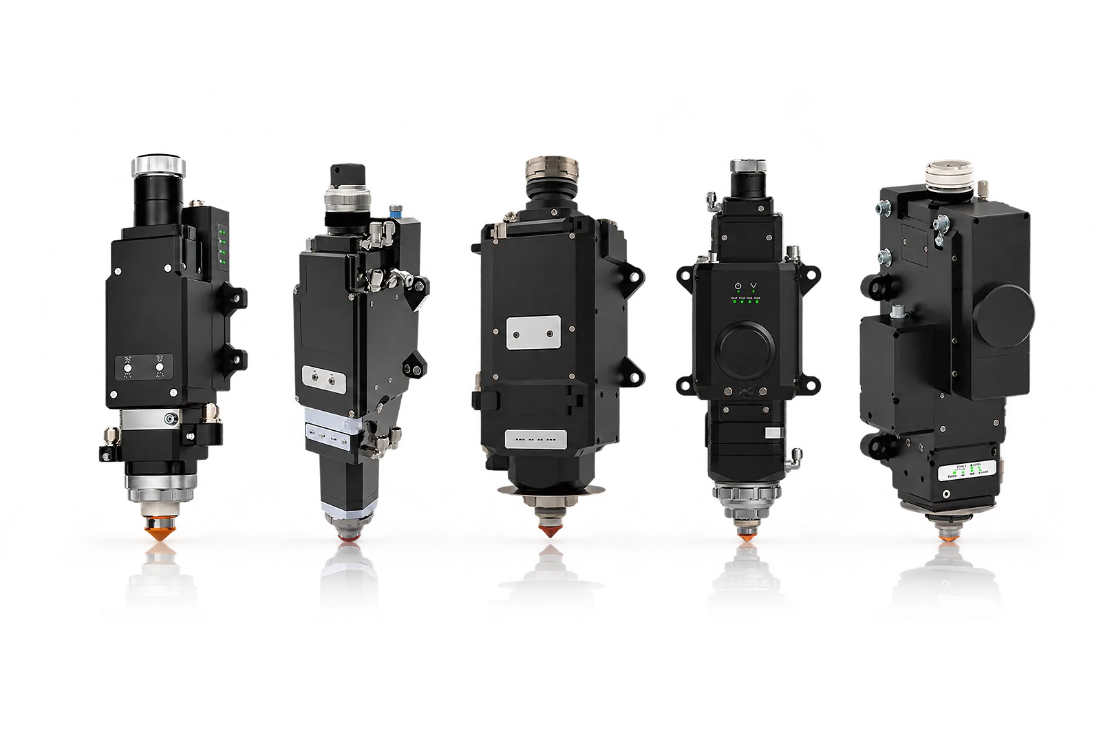
Cutting head
Head functions, focus and assist gas affect the process at the workpiece.
Confirm the head package against the intended edge quality and material samples.
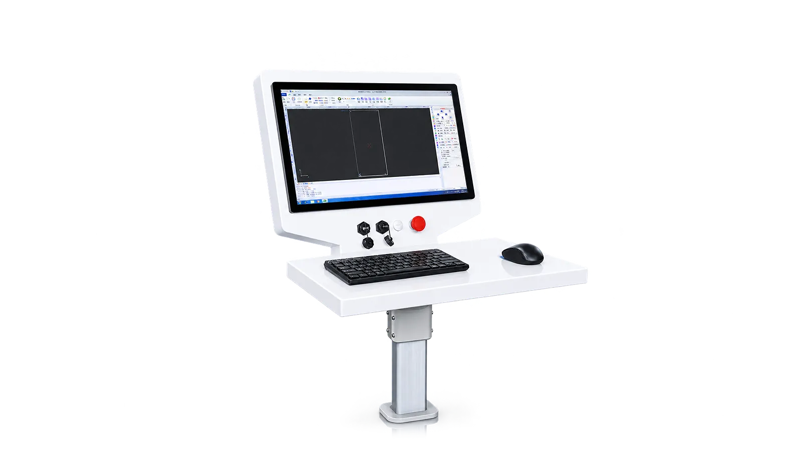
CNC
The selected control package coordinates the drawing-based cutting sequence, height following and edge finding.
Review available functions and production-data interfaces in the supplied software.
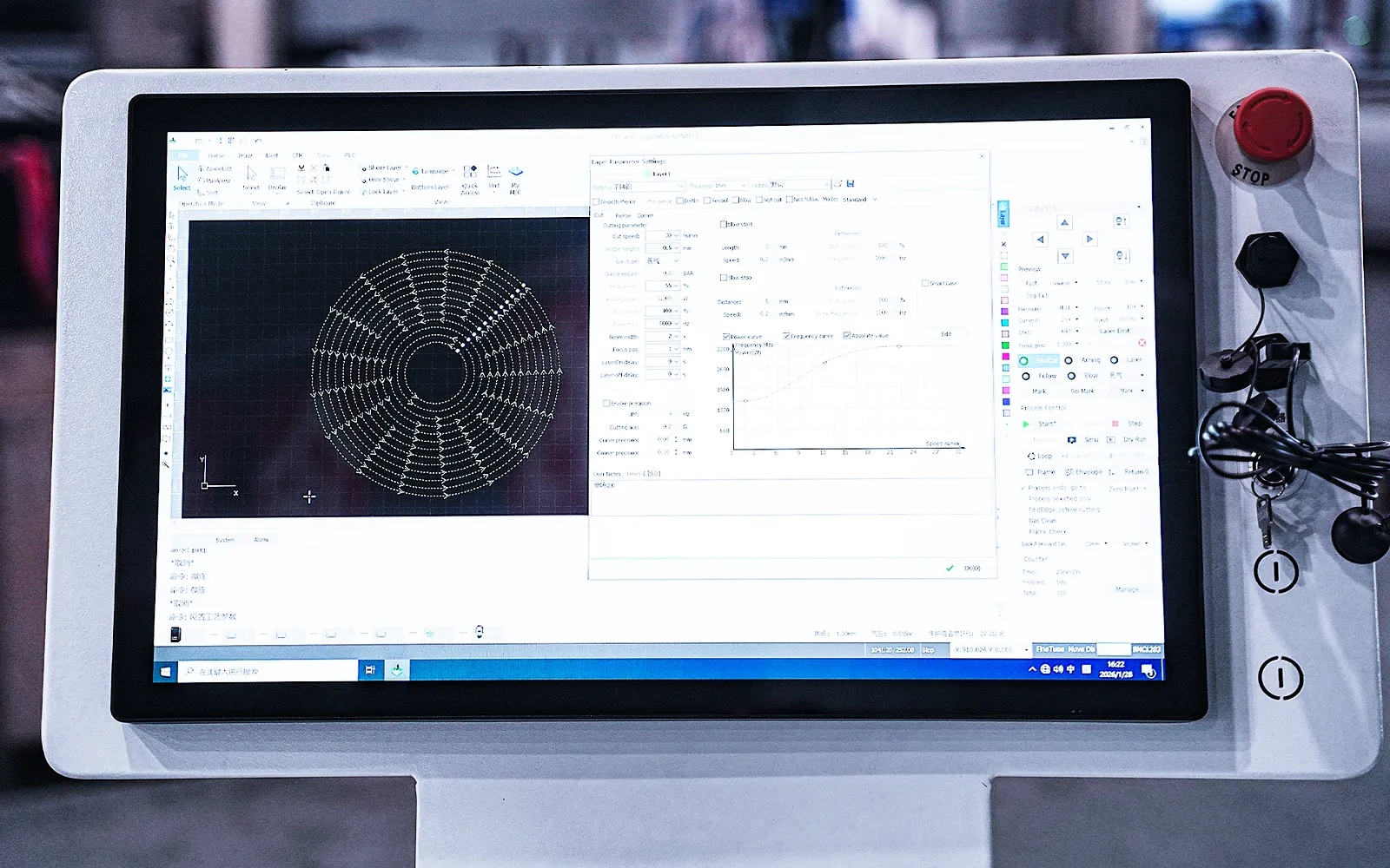
Nesting
Nesting determines how parts are organized into cutting jobs.
Review common-line cutting, remnant handling and reporting for the required workload.
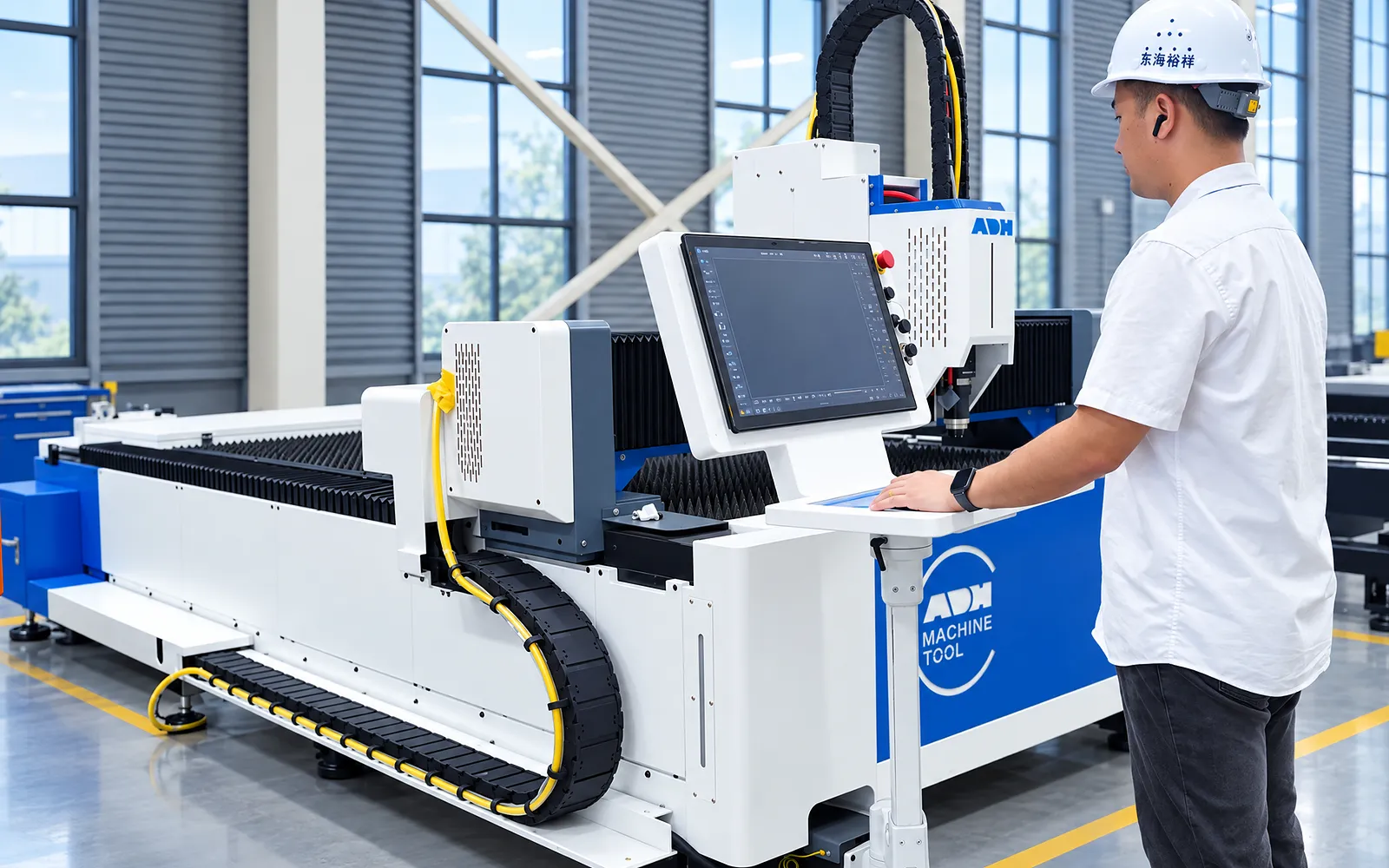
Recovery
Job recovery is part of the selected control package.
Demonstrate how stopped jobs are reviewed and resumed with the delivered software functions.
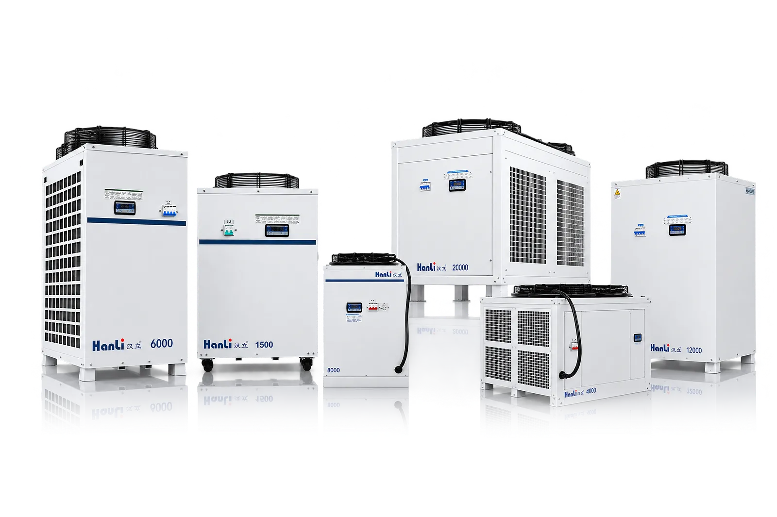
Cooling
Cooling must suit the selected source, laser power and operating duty.
Identify the supplied cooling peripherals, utilities and service access before installation.
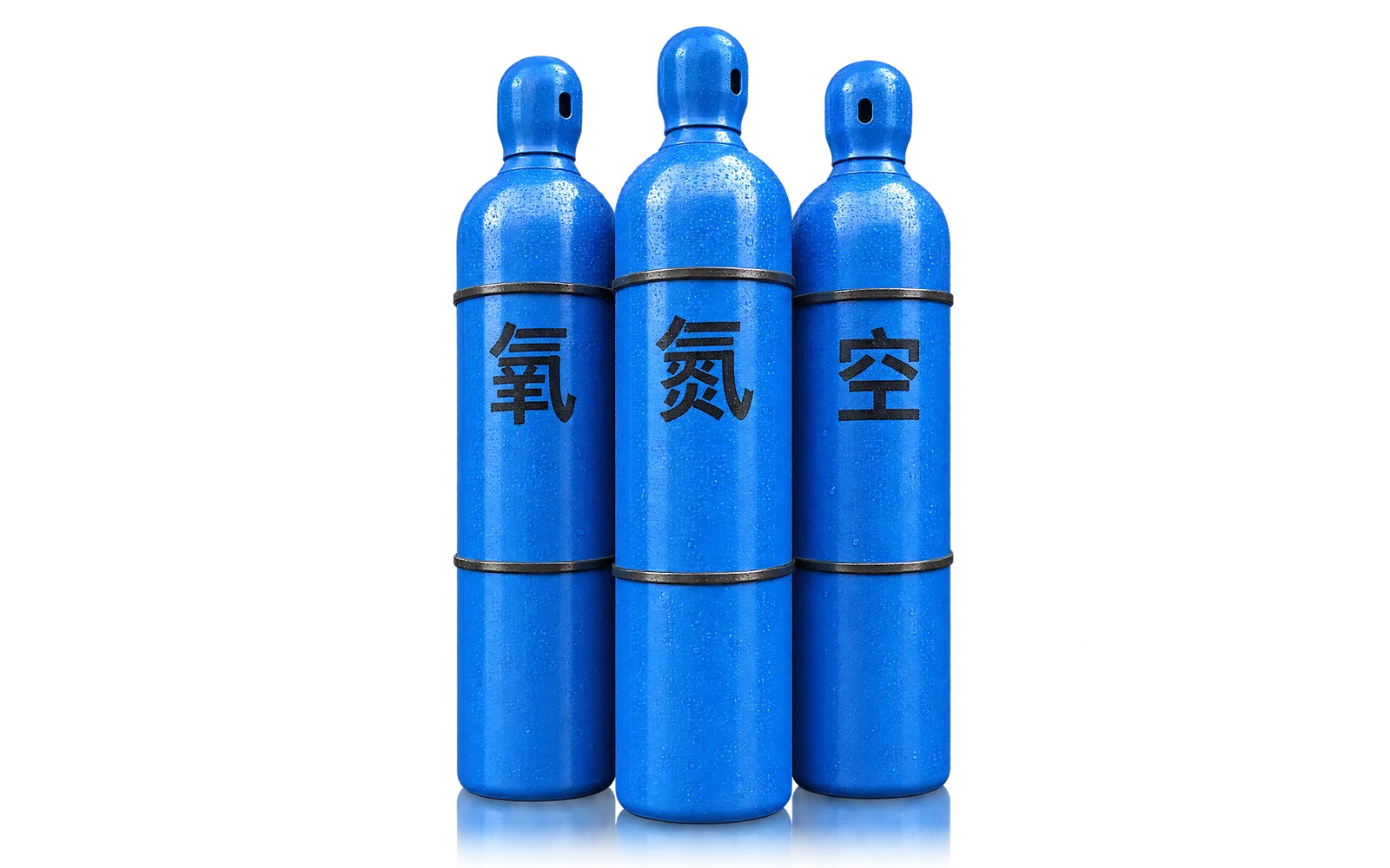
Gas supply
Gas supply supports the selected material and cutting process.
Confirm the supplied equipment and site gas connections for the intended operating duty.
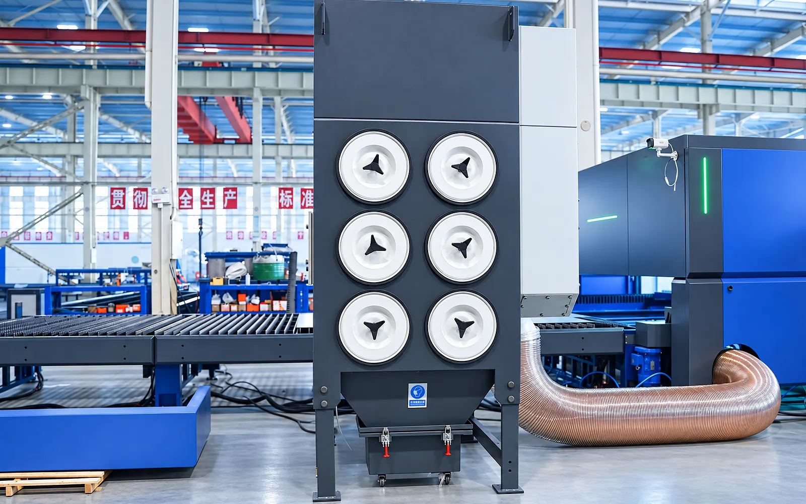
Extraction
Extraction serves the active cutting process and must suit the material and workload.
Identify site connections and allow access for service and clearing process waste.
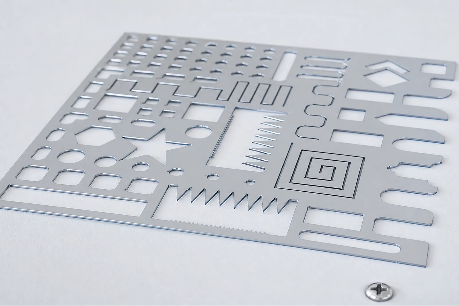
06
A cut trial connects sheet format, material, thickness, gas and programming to the required result. Inspect the finished dimensions and edge condition.
Use the agreed drawing and inspection method. Include loading and part removal when reviewing the practical production cycle.
Model selection
Use the detailed flat-sheet model data; tube-specific fields do not apply to ULF.
Use the exact G or E column for format, power compatibility, travel, precision, speed, acceleration, payload, dimensions and mass.
Extraction, compressor, gas control, nesting, MES and auxiliaries are configuration-dependent.
Confirm material, thickness, utilities, loading, sample and acceptance method.
Related machines & selection
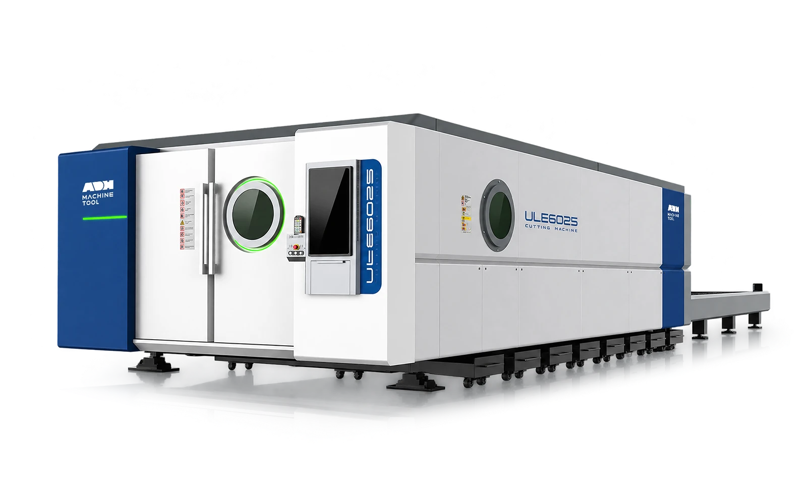
Through the machine lifecycle
Find the training, maintenance guidance and parts support your team needs. Services and availability are confirmed for your machine and location.
Before start-up
Prepare utilities, lifting and the installation area, then coordinate start-up and handover.
Review installation supportBefore production
Build the operator, programming and maintenance skills required for your delivered machine.
Explore trainingIn operation
Get support with the machine model, serial number and a clear description of the issue.
Request technical supportPlanned spares
Identify your machine and component so our team can check compatibility and availability.
Request service or partsSelf-service
Find video guidance for operating and maintaining your ADH machine. Check relevance to your model and configuration.
Browse support videosContract scope
Your quotation or contract defines included services, warranty, exclusions and responsibilities.
Review service scopeProject enquiry
Tell us what you want to make or improve. Technical details and drawings can follow.
Contact ADH
Name, email and a short description are enough to begin.