
01
Material and thickness
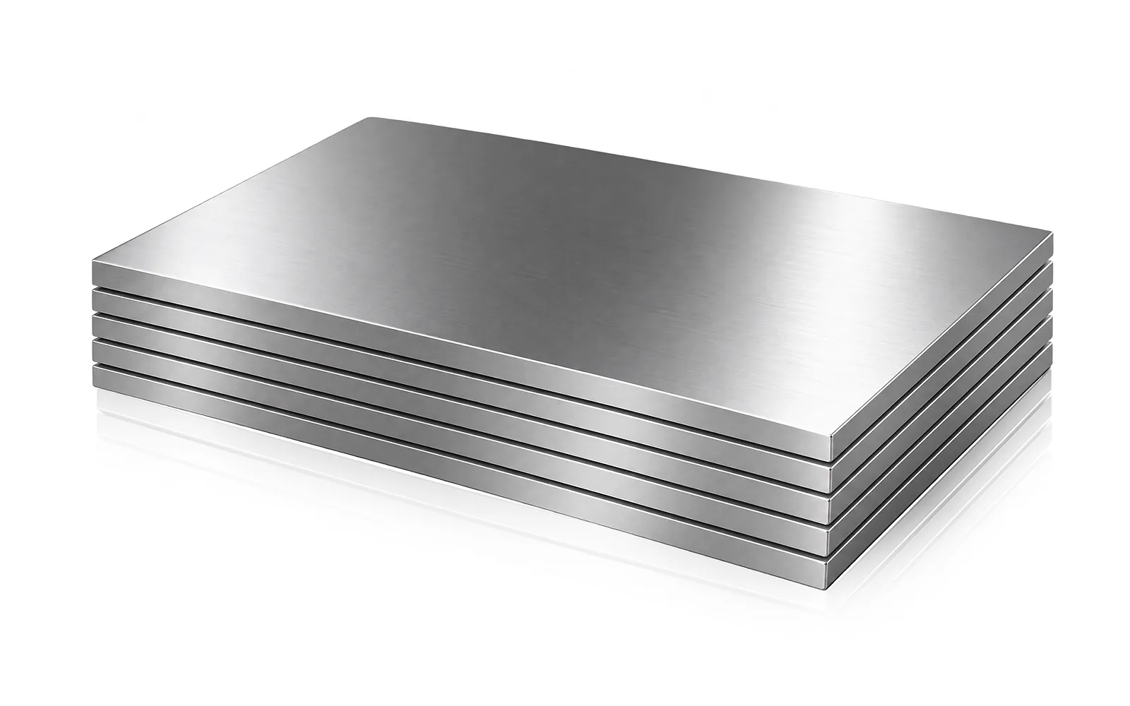
Provide material grade, shear strength, thickness range and surface condition so the published capacity can be interpreted correctly.
Shearing · QC12K/E Series
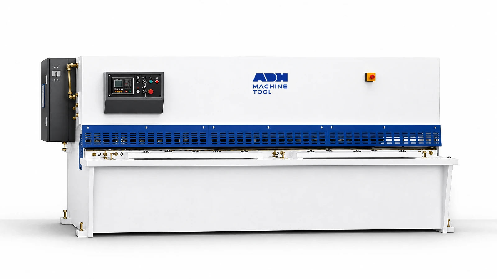
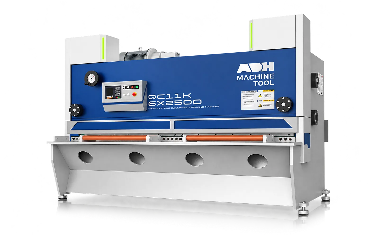
A hydraulic sheet-cutting platform with an arc-swing upper beam, welded frame, material hold-down and programmable backgauge for repeatable production blanking.
Technical specifications
The QC12K-4 × 2500 swing-beam shear is rated for 4 mm thickness across 2,500 mm, with 33 strokes per minute and a 1.5° cutting angle. Compare the width, backgauge travel and stroke rate below, then check the thickness rating against your material strength.
| Model | Cutting Thickness | Cutting Width | Oil Tank | Stroke Rate | Backgauge Range | Cutting Angle | Main Power | Pump | Weight | Overall Dimensions |
|---|---|---|---|---|---|---|---|---|---|---|
| Unit | mm | mm | L | times/min | mm | ° | kW | ml/r | t | L×W×H mm |
| QC12K-4*2500 | 4 | 2500 | 140 | 33 | 20–650 | 1.5 | 7.5 | 25 | 3.6 | 3035×1570×1720 |
| QC12K-4*3200 | 4 | 3200 | 190 | 26 | 20–650 | 1.5 | 7.5 | 25 | 5.7 | 3750×1640×1850 |
| QC12K-4*4000 | 4 | 4000 | 190 | 23 | 20–800 | 1.5 | 7.5 | 25 | 7.7 | 4550×1900×1900 |
| QC12K/E-4*5000 | 4 | 5000 | 320 | 16 | 20–800 | 1.5 | 7.5 | 25 | 8.8 | 5700×1900×2000 |
| QC12K/E-4*6000 | 4 | 6000 | 440 | 12 | 20–800 | 1.5 | 15 | 32 | 17.5 | 6500×2460×2250 |
| QC12K-6*2500 | 6 | 2500 | 190 | 17 | 20–650 | 2 | 7.5 | 25 | 5.7 | 3050×1650×1900 |
| QC12K-6*3200 | 6 | 3200 | 190 | 17 | 20–650 | 1.5 | 7.5 | 25 | 6.7 | 3750×1650×1900 |
| QC12K-6*4000 | 6 | 4000 | 190 | 15 | 20–800 | 1.5 | 7.5 | 25 | 8.4 | 4550×2000×2000 |
| QC12K/E-6*5000 | 6 | 5000 | 320 | 11 | 20–800 | 1.5 | 15 | 32 | 13.0 | 5700×2450×2300 |
| QC12K/E-6*6000 | 6 | 6000 | 440 | 8 | 20–800 | 1.5 | 15 | 32 | 20.1 | 6550×2470×2500 |
| QC12K/E-8*2500 | 8 | 2500 | 190 | 13 | 20–650 | 2 | 11 | 32 | 6.0 | 3060×1650×1900 |
| QC12K/E-8*3200 | 8 | 3200 | 190 | 13 | 20–650 | 1.5 | 11 | 32 | 7.0 | 3760×1650×1900 |
| QC12K/E-8*4000 | 8 | 4000 | 190 | 12 | 20–800 | 1.5 | 15 | 32 | 9.1 | 4560×1960×1920 |
| QC12K/E-8*5000 | 8 | 5000 | 320 | 10 | 20–800 | 1.5 | 18.5 | 40 | 13.2 | 5600×2360×2180 |
| QC12K/E-8*6000 | 8 | 6000 | 440 | 9 | 20–800 | 1.5 | 18.5 | 40 | 22.1 | 6600×2450×2500 |
| QC12K/E-10*2500 | 10 | 2500 | 190 | 13 | 20–800 | 2 | 15 | 32 | 7.2 | 3050×2000×1920 |
| QC12K/E-10*3200 | 10 | 3200 | 190 | 13 | 20–800 | 1.5 | 15 | 32 | 8.8 | 3800×2000×1920 |
| QC12K/E-10*4000 | 10 | 4000 | 400 | 9 | 20–800 | 1.5 | 22 | 50 | 12.2 | 4700×2100×2200 |
| QC12K/E-10*6000 | 10 | 6000 | 440 | 6 | 20–800 | 1.5 | 22 | 50 | 28.3 | 6600×2100×2300 |
| QC12K/E-12*2500 | 12 | 2500 | 400 | 12 | 20–800 | 2 | 22 | 50 | 10.1 | 3170×2150×2180 |
| QC12K/E-12*3200 | 12 | 3200 | 400 | 10 | 20–800 | 2 | 22 | 50 | 11.8 | 3800×2150×2180 |
| QC12K/E-12*4000 | 12 | 4000 | 400 | 8 | 20–800 | 1.75 | 22 | 50 | 14.2 | 4700×2280×2200 |
| QC12K/E-12*5000 | 12 | 5000 | 440 | 6 | 20–800 | 2 | 30 | 63 | 19.6 | 5800×2450×2400 |
| QC12K/E-12*6000 | 12 | 6000 | 440 | 5 | 20–800 | 2 | 30 | 63 | 32 | 6600×2600×2700 |
| QC12K/E-16*2500 | 16 | 2500 | 400 | 13 | 20–800 | 2.5 | 22 | 50 | 11.3 | 3250×2300×2200 |
| QC12K/E-16*3200 | 16 | 3200 | 400 | 10 | 20–800 | 2 | 22 | 50 | 13.0 | 3870×2300×2180 |
| QC12K/E-16*4000 | 16 | 4000 | 600 | 9 | 20–800 | 1.75 | 22 | 50 | 17.6 | 4700×2575×2200 |
| QC12K/E-16*5000 | 16 | 5000 | 600 | 7 | 20–800 | 2.5 | 30 | 63 | 24.7 | 5900×2600×2700 |
| QC12K/E-16*6000 | 16 | 6000 | 600 | 5 | 20–800 | 2.5 | 30 | 63 | 38.0 | 6600×2700×2900 |
| QC12K/E-20*2500 | 20 | 2500 | 500 | 8 | 20–800 | 2.5 | 30 | 80 | 14.7 | 3300×2580×2300 |
| QC12K/E-20*3200 | 20 | 3200 | 500 | 7 | 20–800 | 2.5 | 30 | 80 | 16.5 | 4150×2600×2500 |
| QC12K/E-20*4000 | 20 | 4000 | 550 | 5 | 20–800 | 2.5 | 30 | 80 | 23.7 | 4850×2600×2800 |
Cutting inputs
Nominal thickness is not enough; grade, width, edge criteria, support and safety define the practical machine selection.
01
Provide material grade, shear strength, thickness range and surface condition so the published capacity can be interpreted correctly.
02
Define cutting width, minimum and maximum cut length, backgauge range, blank size and the downstream forming process.
03
Record straightness, squareness, burr and edge requirements together with stroke rate, batch size and changeover pattern.
04
Confirm front support, rear handling, controller functions, blade-gap setup, guarding, foot control and destination requirements.
Machine in operation
See the QC12K/E cutting sequence and assess sheet support, positioning and removal for your work.
Watch on YouTube (opens in a new tab)Product systems
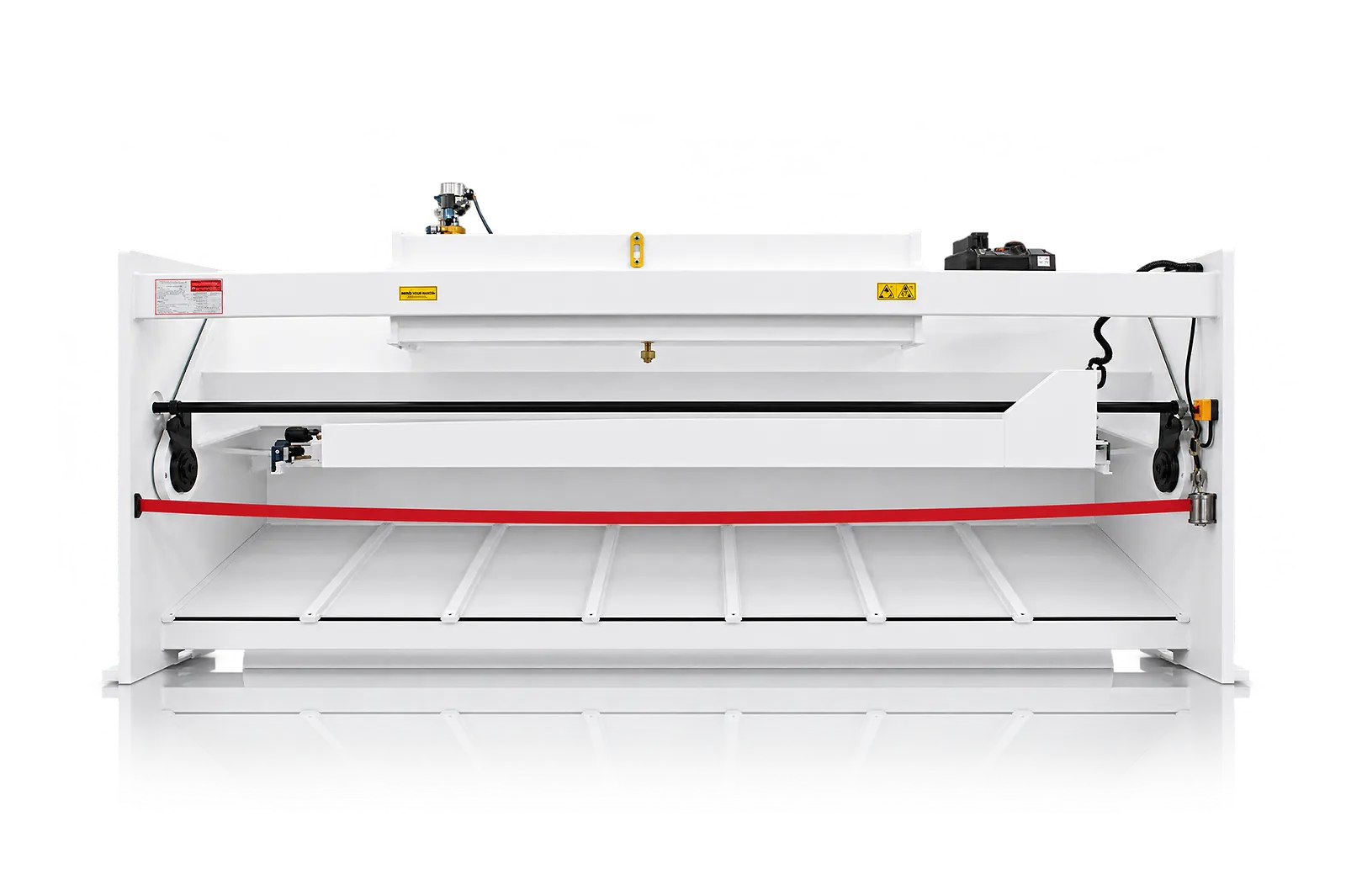
QC12K/E shears use an upper beam that swings around a pivot. Blade setup, sheet holding and the reference edge work together to determine the cut.
Swing beam
The welded frame carries the worktable and pivoting upper beam. Hydraulic motion drives the stroke.
Select working length, thickness and stated material capacity from the same QC12K/E model.
Hold-downs
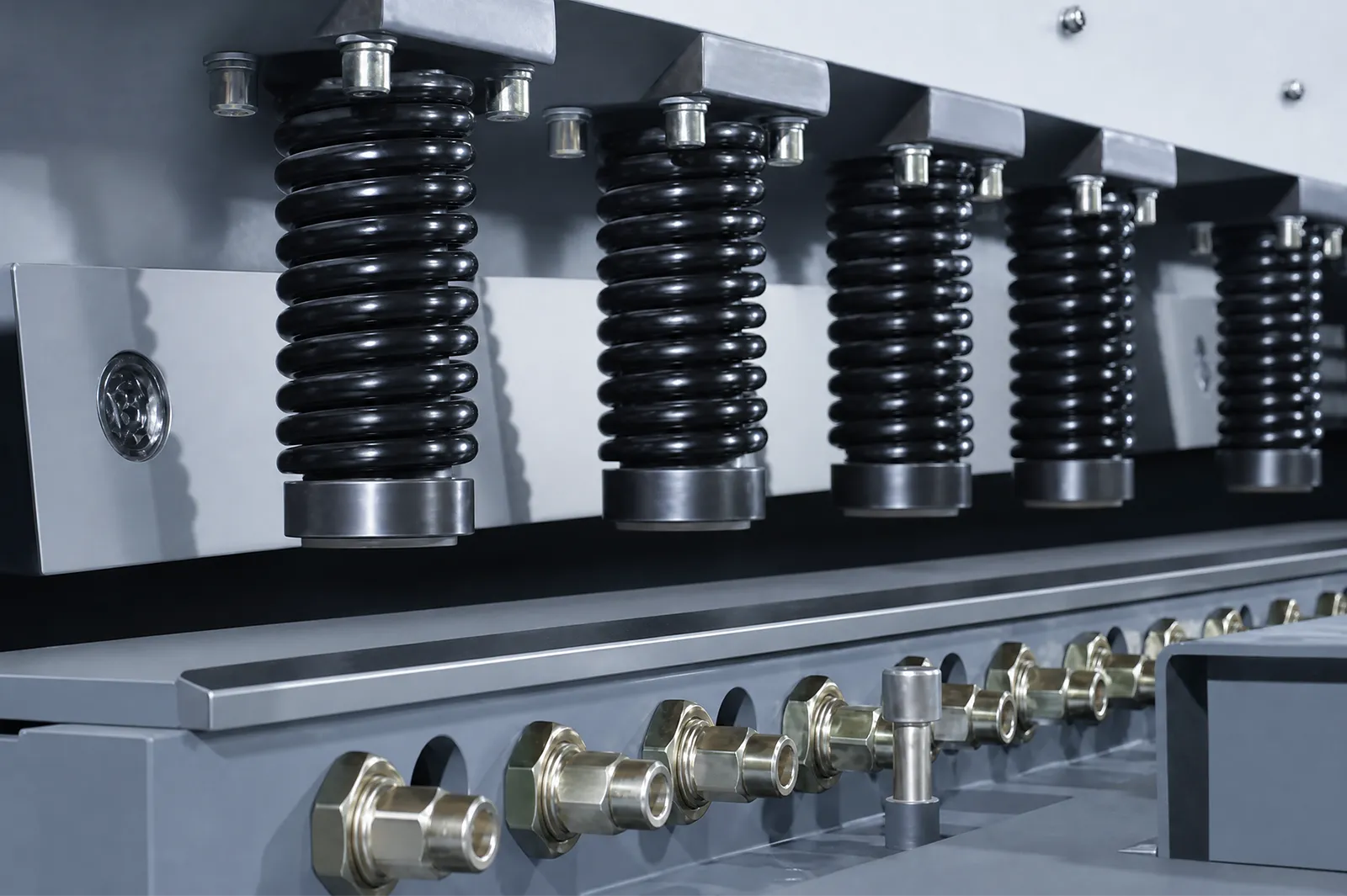
Hold-downs secure the sheet before the blades separate the material.
Review the holding and support arrangement for the intended sheet. Hydraulic and stroke-rate data remain model-specific.
Blade geometry
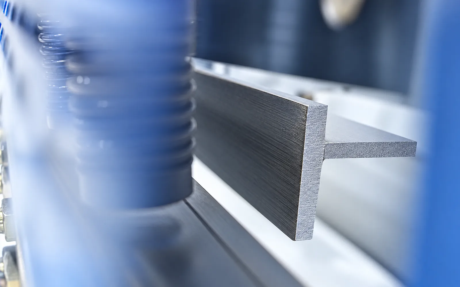
The selected blade set and blade condition affect material separation.
Review the tooling for your normal work and the required cut quality.
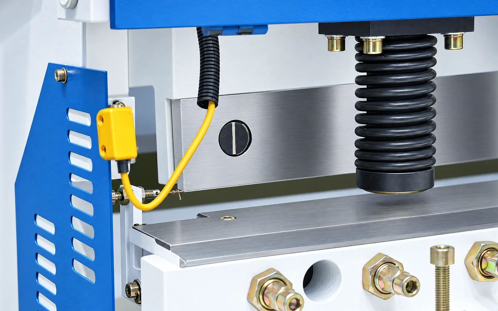
Blade clearance
The gap between the cutting edges must suit material and thickness.
Review the adjustment method and validate the setup on the intended sheet.
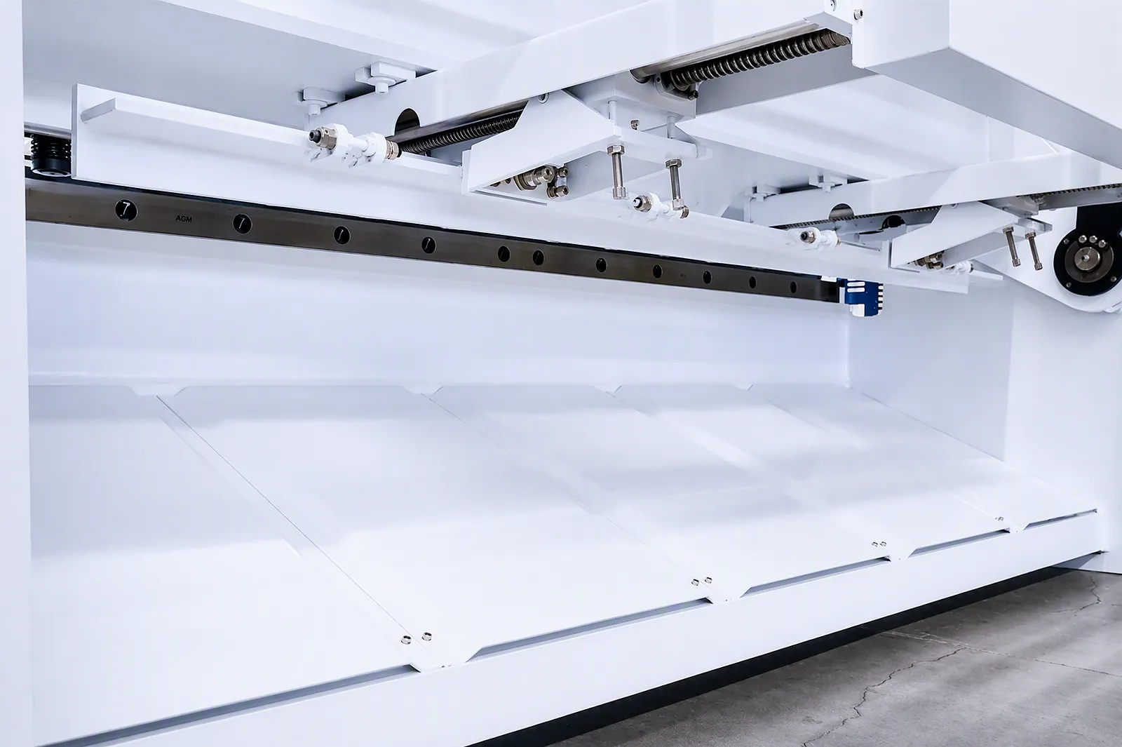
Backgauge
The backgauge locates the sheet for the required cut length.
Check short cuts, access and positioning requirements. Servo positioning depends on the supplied package.
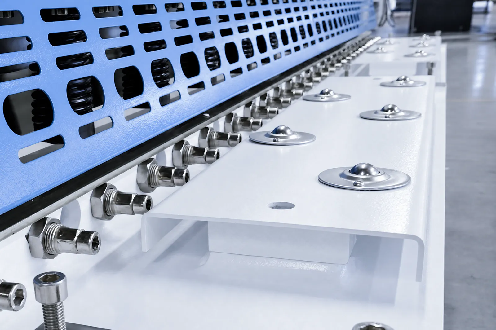
Sheet support
The worktable and front supports help the operator support and present the sheet.
Review stock weight and remnant removal. Rear support depends on the selected package.
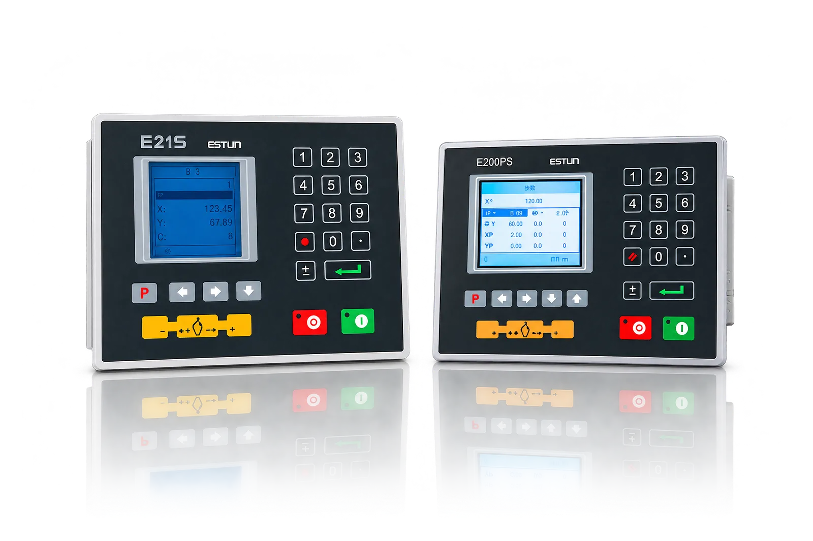
Controller
The controller manages the supplied programming and positioning functions.
Review how lengths are entered, recalled and adjusted. Automatic setup functions vary by configuration.
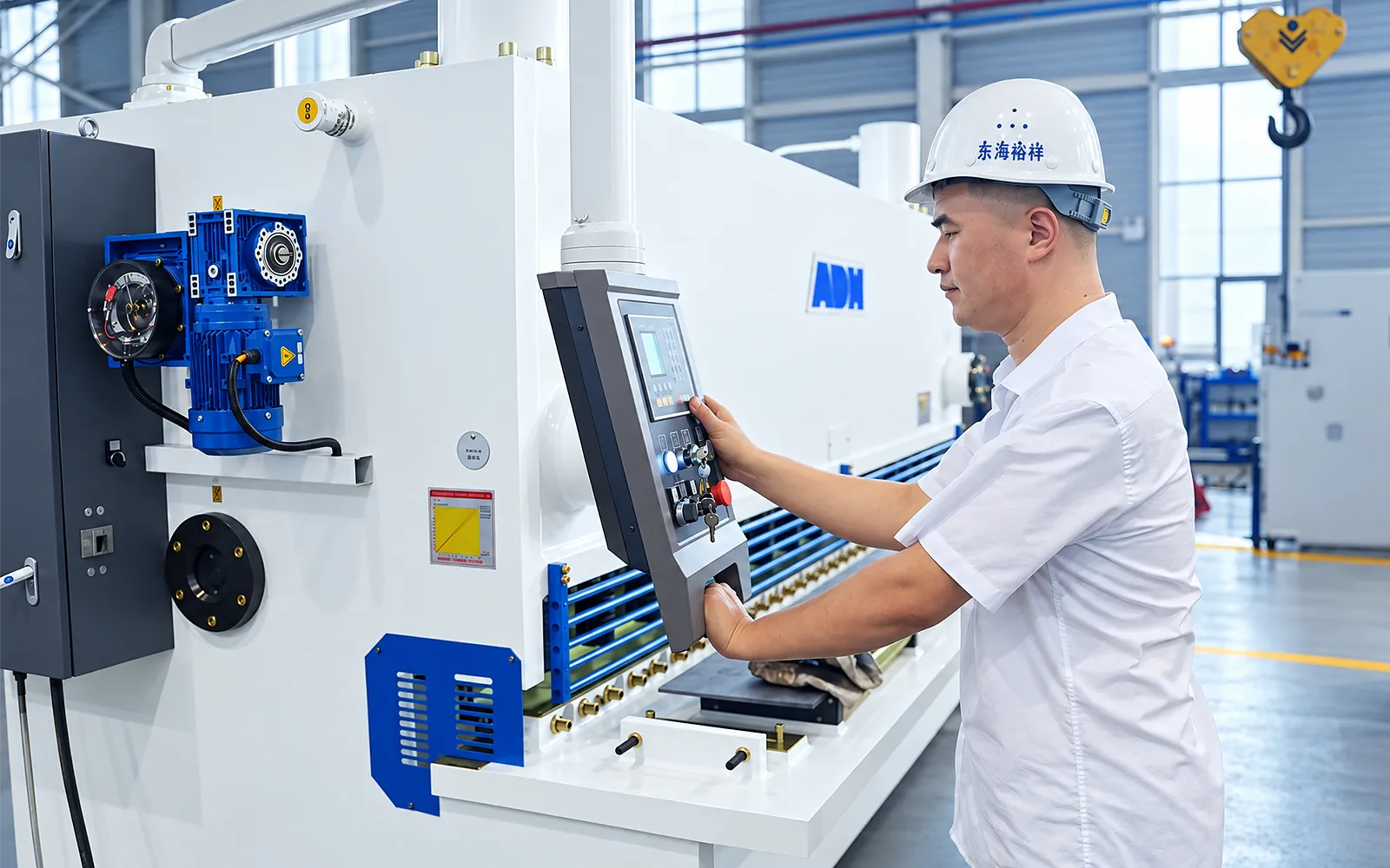
Guarded access
Operator and rear access must be reviewed alongside the cutting workflow.
Confirm throat protection, foot controls, emergency stops and any optical devices in the delivered layout.
05
A sample cut brings material, blade setup, holding and positioning into one review. Inspect the finished dimension and edge against the drawing.
Use the intended material and thickness, with the planned support and removal method. Agree the inspection criteria before evaluating the result.
Select the Package Against Material and Acceptance Criteria
Use the selected QC12K/E model data for numeric selection; material strength and delivered options determine how each row is applied.
Use the selected QC12K/E model row for thickness, width, stroke rate, backgauge, angle, power, pump, weight and dimensions.
Controller, servo backgauge, gap or stroke functions, rear support, light protection, guarding and blade grade require confirmation.
Confirm material shear strength, cut quality criteria, blade setup, support and handling, electrical supply and the complete safety package.
Related machines & selection
Through the machine lifecycle
Find the training, maintenance guidance and parts support your team needs. Services and availability are confirmed for your machine and location.
Before start-up
Prepare utilities, lifting and the installation area, then coordinate start-up and handover.
Review installation supportBefore production
Build the operator, programming and maintenance skills required for your delivered machine.
Explore trainingIn operation
Get support with the machine model, serial number and a clear description of the issue.
Request technical supportPlanned spares
Identify your machine and component so our team can check compatibility and availability.
Request service or partsSelf-service
Find video guidance for operating and maintaining your ADH machine. Check relevance to your model and configuration.
Browse support videosContract scope
Your quotation or contract defines included services, warranty, exclusions and responsibilities.
Review service scopeProject enquiry
Tell us what you want to make or improve. Technical details and drawings can follow.
Contact ADH
Name, email and a short description are enough to begin.