
01 · Structural sections
H-beams and open profiles
Prepare cut ends, holes, notches and bevels on H-sections, I-sections, channels and angles. The proposal lists a 150–1,500 mm H-section web range and 100–600 mm flange range.
ULH series · Profile, plate & tube
Bring beam cut-off, holes, notches and bevel preparation into one cutting workflow. The ULH platform combines structural-profile, large-format plate and heavy-tube processing for steel fabricators, with scanning and five-axis control matched to the workpiece.
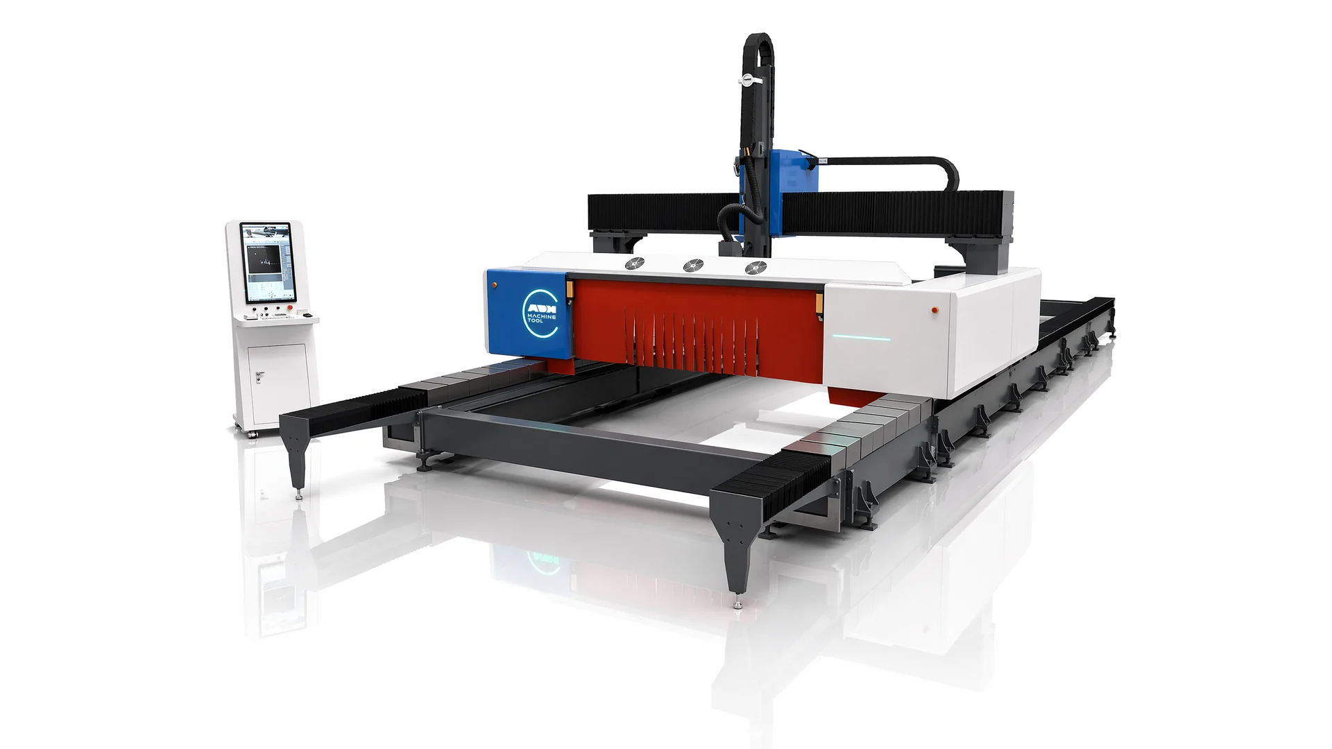
ULH30035-20000W configuration
The ULH30035-20000W uses a 20 kW laser and provides a 30,000 × 3,500 mm plate area for straight cuts. Its H-section range covers web heights of 150–1,500 mm and flange widths of 100–600 mm. For bevels, match the head travel and clearance to the actual section drawing.
| Parameter | Value | Note |
|---|---|---|
| Model | ULH30035-20000W | Configuration described in the 11 December 2025 technical proposal. |
| Laser power | 20 kW | Raycus fiber laser source. |
| Plate cutting area — straight cuts | 30,000 × 3,500 mm | Bevel-cut working width is confirmed with the application. |
| Y-axis travel | 30,000 mm | Longitudinal travel. |
| X-axis travel | 3,550 mm | Travel differs from the usable straight-cut width. |
| Z-axis travel | 1,200 mm | Cutting-head lift. |
| H-section web range | 150–1,500 mm | Workpiece section dimensions; thickness and shape require review. |
| H-section flange range | 100–600 mm | Confirm the complete section drawing and tool access. |
| Maximum round tube diameter | 1,200 mm | With the heavy-duty tube package. |
| Maximum square tube side | 1,200 mm | With the heavy-duty tube package; verify corners and clamping. |
| Maximum tube length | 12,000 mm | Tube limit is separate from the 30 m longitudinal travel. |
| Maximum tube load | 14 t | Tube-processing capacity; handling and supports must suit the workpiece. |
| X/Y positioning accuracy | ≤ ±0.1 mm/m | Machine-axis specification, not finished-part tolerance. |
| X/Y repeat positioning accuracy | ±0.05 mm | Machine-axis repeatability. |
| Maximum X/Y positioning speed | 30 m/min | Positioning speed, not a guaranteed cutting feed rate. |
| A-axis swing | ±45° | Mechanical axis range; achievable bevel depends on the part. |
| B-axis swing | ±90° | Mechanical axis range; achievable bevel depends on the part. |
| Overall dimensions (L × W × H) | Approx. 36,000 × 5,300 × 4,600 mm | Confirm the final installation drawing and access clearances. |
| Electrical supply in this proposal | 380 V / 50 Hz | Confirm the supply package for the destination country. |
Bevel-cut plate width is specified during application review. Section capacity, mechanical axis travel and finished-part accuracy describe different limits; none should be substituted for another.
Three processing routes
The configuration shown is the ULH30035-20000W, combining a 20 kW source with a long-travel platform. Start with the section and operations your workshop needs.
01 · Structural sections
Prepare cut ends, holes, notches and bevels on H-sections, I-sections, channels and angles. The proposal lists a 150–1,500 mm H-section web range and 100–600 mm flange range.
02 · Plate
Use the 30,000 × 3,500 mm straight-cut area for long plate and nested components. Specify material, thickness, minimum features and the required edge condition.
03 · Heavy tube
The specified tube package covers round and square sections up to 1,200 mm, lengths up to 12 m and loads up to 14 t. Confirm the complete section, clamping and support arrangement.
Machine systems
Scanning, motion control and the cutting package work together. Review each system against your stock variation, connection details and production sequence.
Contour scanning
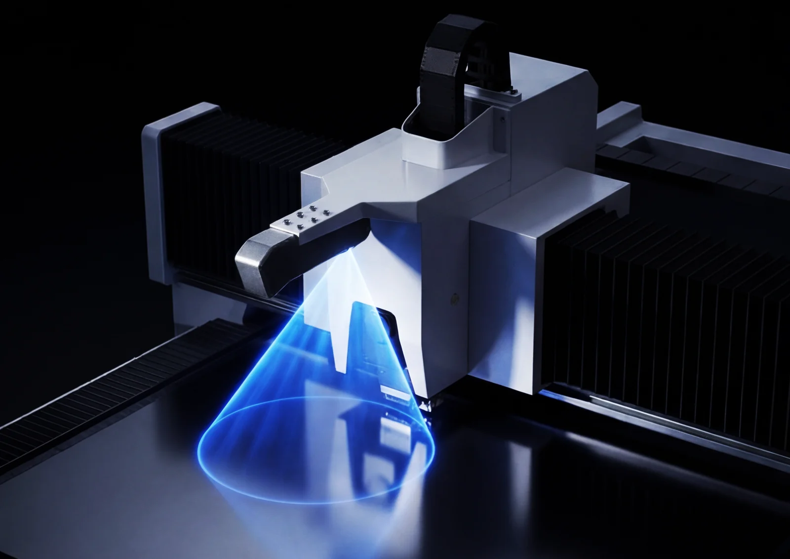
The BCW600B scanning system captures the profile surface and builds a point-cloud model. Comparing the measured section with the design lets the control compensate the cutting path for variation in rolled stock.
Use representative incoming sections to verify alignment, feature location and compensation before approving the process.
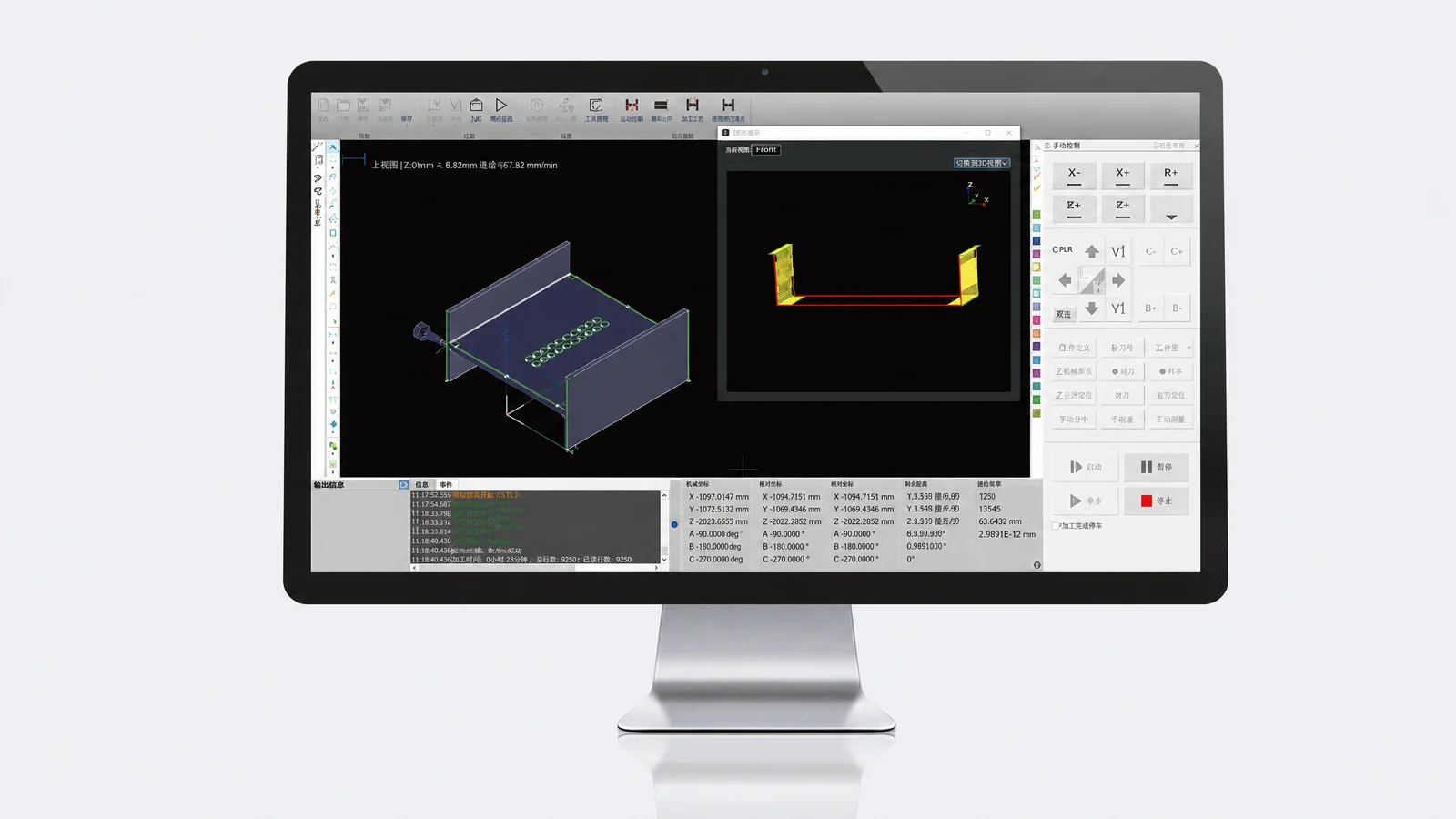
FSCUT9200 and TubesT
FSCUT9200 coordinates the profile-cutting axes and tool-centre-point control. The proposal includes Tekla .nc1, .xml and .step input and TubesT three-dimensional nesting.
Check your exported files, feature recognition, marking and nesting requirements using actual production drawings.
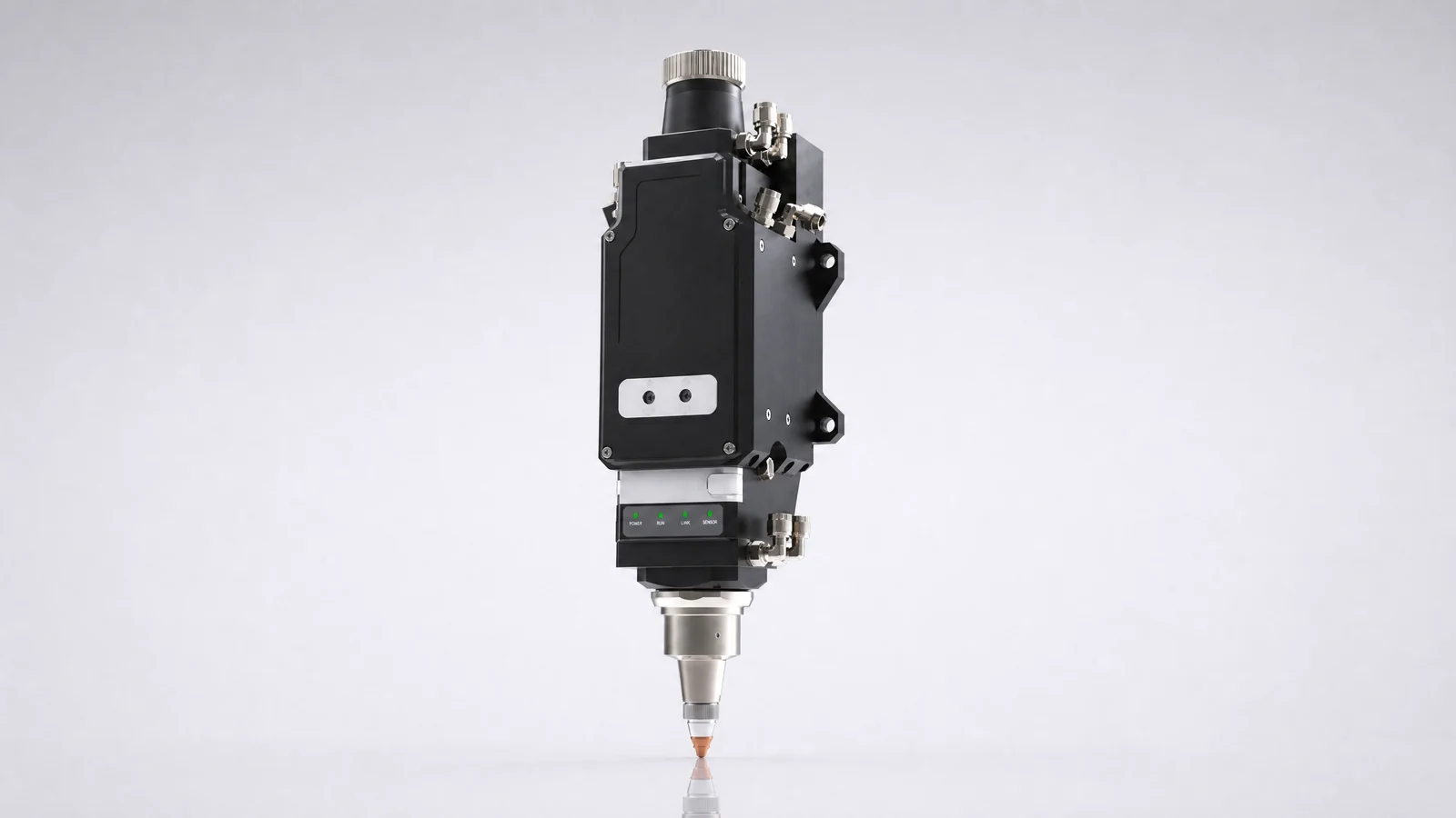
A/B swing-head assembly
The specified BOCI BLT462P cutting head works with the A/B swing assembly for three-dimensional contours and bevel preparation. The proposal lists A-axis travel of ±45° and B-axis travel of ±90°.
The required bevel angle, root face, material thickness and head clearance determine the usable process. Validate the finished joint geometry on a representative part.
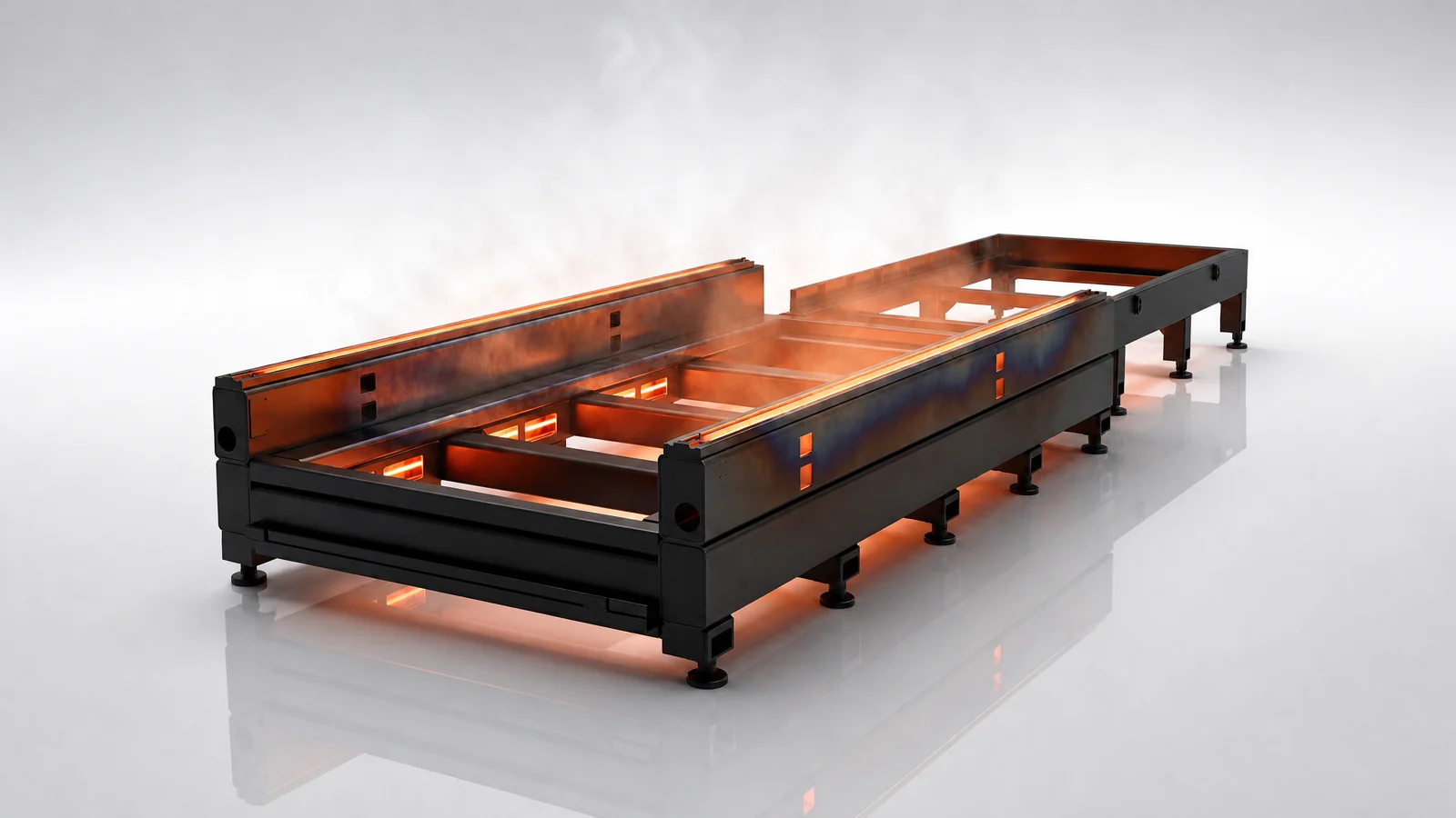
Structure and alignment
A segmented welded bed, stress-relief processing and machined mounting surfaces provide the basis for the long-travel platform. Rail alignment and full-travel calibration form part of machine setup.
Specify stock mass, lifting access, support positions and finished-part removal together. A dual-station table arrangement is an option in the proposal.
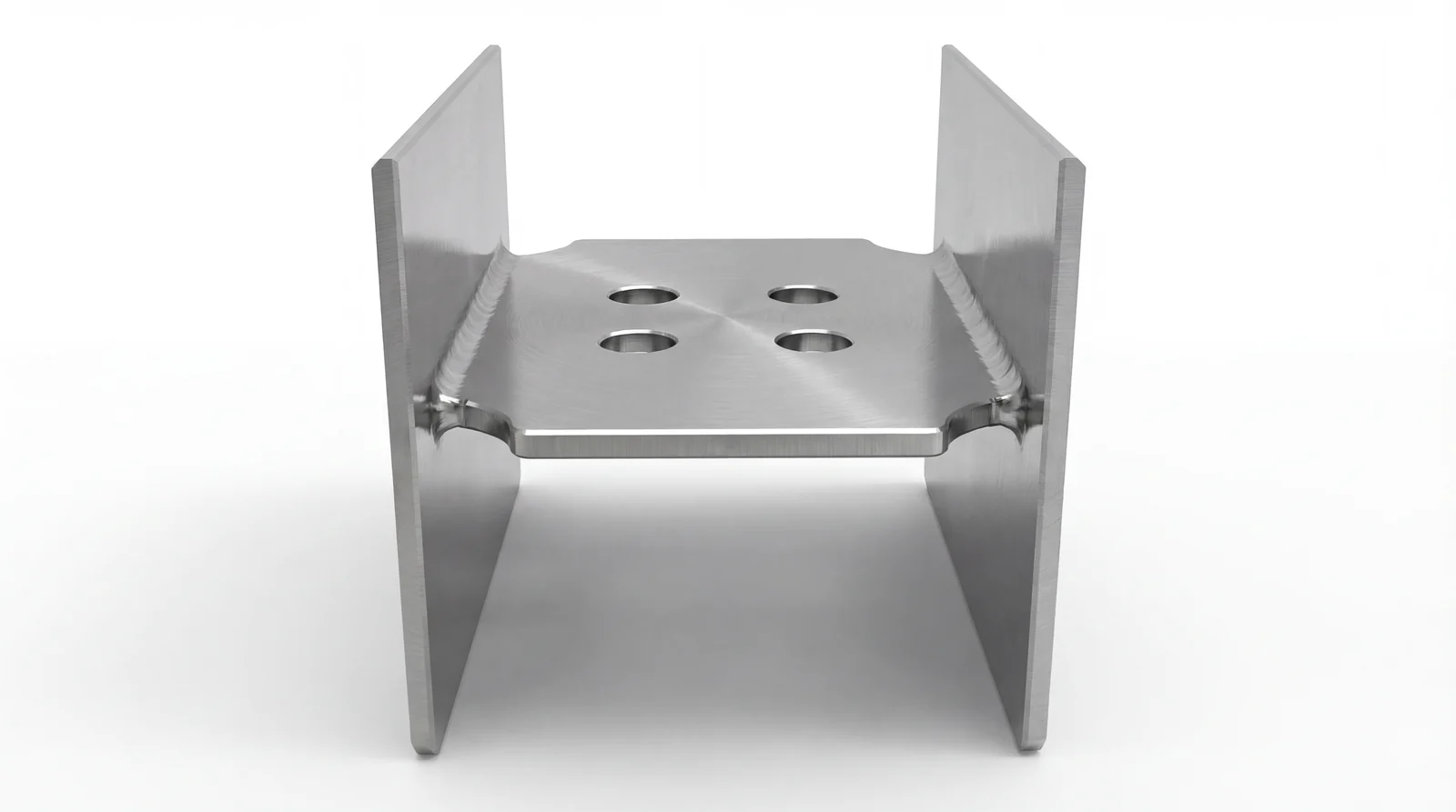
Part preparation
Combine cut-off, hole cutting, notching, bevel preparation and marking where the drawing and process allow. The illustrated H-section shows the kinds of features to discuss; it is not an inspection record.
Agree hole size and spacing, end geometry, bevel condition and any remaining machining. Check the sample against the connection drawing before changing the production route.
Customer installation
Jiuwu Steel Structure brought more beam cutting and connection preparation in house with an ULH26030, 20 kW laser and 26 m processing travel.
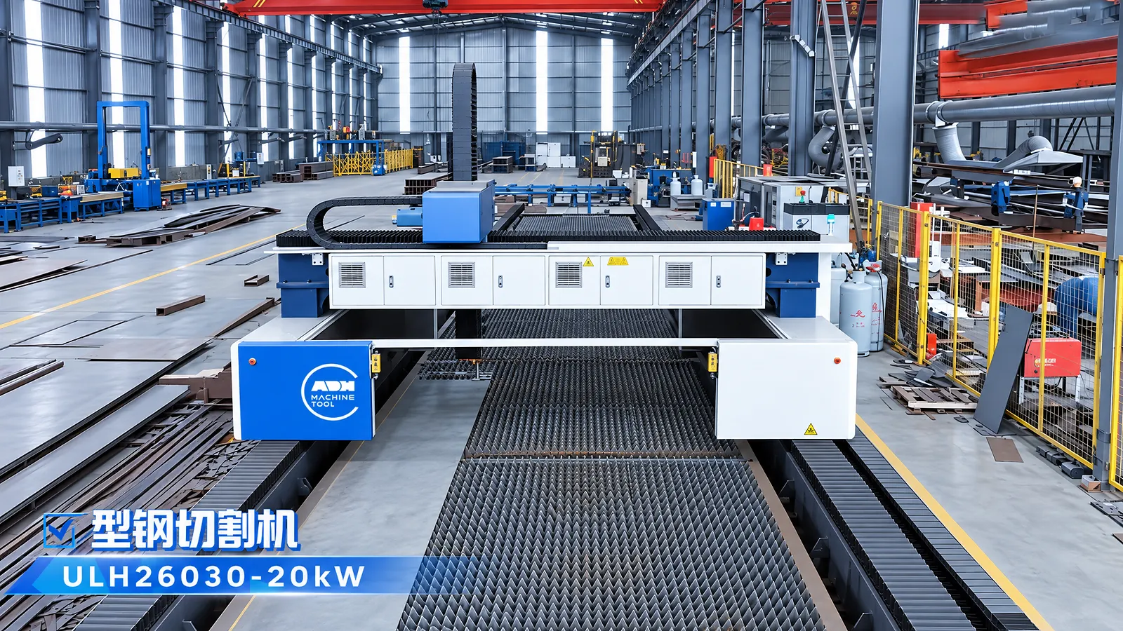
Structural steel · Henan, China
Bringing beam cutting and connection preparation together, with fewer transfers between cutting, drilling and milling.
Read Jiuwu Steel Structure caseThe Jiuwu case describes beam holes, flange notches, cut-off operations and the handling steps around them. Its reported outcomes belong to that customer's installation and production conditions.
The installed ULH26030 is a different configuration from the ULH30035-20000W specification sheet above. Use the case to examine the workflow, then match the equipment to your own parts.
Explore steelwork and building components →Before ordering
A long machine needs a complete plan for loading, foundations, utilities and inspection. These inputs shape the delivered package.
Send the section drawing, steel grade, wall thickness, stock and finished lengths, mass, batches and joint details. Include sample files from your design software.
Plan around the approximate 36 × 5.3 × 4.6 m machine envelope. Confirm foundations, crane access, guarding, extraction, electrical supply, assist gas, cooling and maintenance clearances.
Agree sample parts and measurement methods for holes, notches, cut ends and bevels. Check machine motion, representative cutting, handling and operator training against the signed technical agreement.
Configuration and lifecycle
The reference package combines a Raycus 20 kW source, FSCUT9200 control, BLT462P head, BCW600B scanner, TubesT nesting and dual-circuit cooling. Confirm component selection, tube equipment, optional workstations, training and warranty terms for your order and destination.
Through the machine lifecycle
Find the training, maintenance guidance and parts support your team needs. Services and availability are confirmed for your machine and location.
Before start-up
Prepare utilities, lifting and the installation area, then coordinate start-up and handover.
Review installation supportBefore production
Build the operator, programming and maintenance skills required for your delivered machine.
Explore trainingIn operation
Get support with the machine model, serial number and a clear description of the issue.
Request technical supportPlanned spares
Identify your machine and component so our team can check compatibility and availability.
Request service or partsSelf-service
Find video guidance for operating and maintaining your ADH machine. Check relevance to your model and configuration.
Browse support videosContract scope
Your quotation or contract defines included services, warranty, exclusions and responsibilities.
Review service scopeProject enquiry
Tell us what you want to make or improve. Technical details and drawings can follow.
Contact ADH
Name, email and a short description are enough to begin.