
01
Profile and dimensions
Provide round, square or approved profiles, outside dimensions, wall, length, weight, straightness and surface condition.
Tube Laser Cutting | ULT Series
A configurable tube-cutting family with two- and three-chuck routes selected for profile, stock length, payload, remnant target and handling.
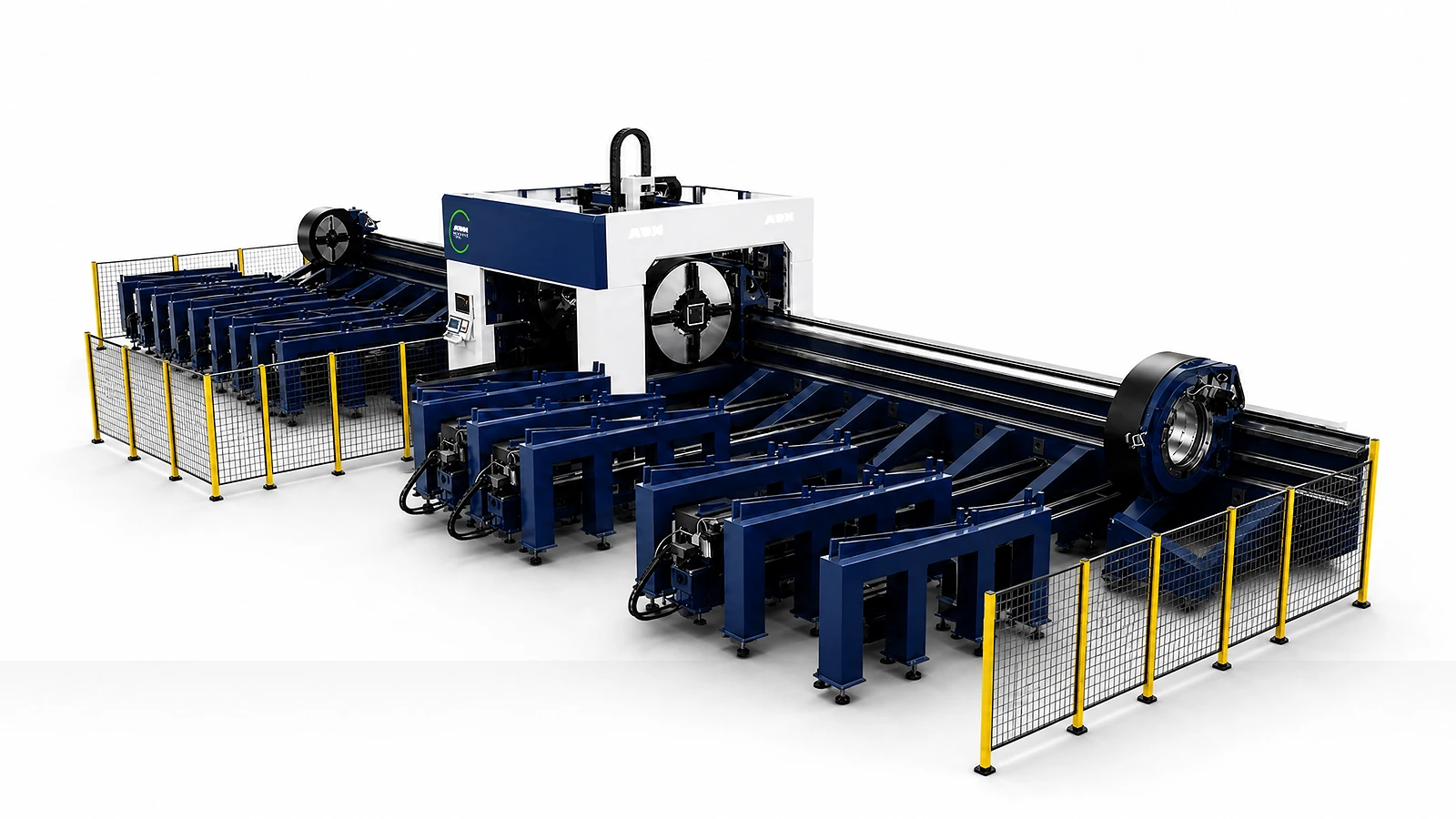
Technical specifications
Select the model family, chuck count and package together. Stock length follows the corresponding 6, 9 or 12 m model. Pneumatic loading has separate tube-size and load limits. Rated chuck speed is specified at a motor speed of 1500 rpm.
| Model Configuration | Chuck Architecture | Chuck Package | Max Stock Length (by model) | Round Range | Square Range | X Travel | Z Travel | Positioning Accuracy | Repeatability | Max Coupled Speed | Max Acceleration | Rated Chuck Speed | Max Chuck Load | Pneumatic Loading Limits |
|---|---|---|---|---|---|---|---|---|---|---|---|---|---|---|
| Unit | m | mm | mm | mm | mm | mm/m | mm/m | m/min | G | r/min | kg | |||
| 2-chuck A · ULT6016/9016/12016 | 2-chuck | A | 6 / 9 / 12 | Ø10–160 | 160×160 | 300 | 250 | ±0.04 | ±0.03 | 100 | 1.2 | 53.5 | 150 | Square tube: circumscribed diameter ≤160 mm |
| 2-chuck B · ULT6016/9016/12016 | 2-chuck | B | 6 / 9 / 12 | Ø10–160 | 160×160 | 300 | 250 | ±0.04 | ±0.03 | 100 | 1.2 | 53.5 | 160 | Square tube: circumscribed diameter ≤160 mm |
| 2-chuck A · ULT6024/9024/12024 | 2-chuck | A | 6 / 9 / 12 | Ø10–240 | 227×227 | 400 | 300 | ±0.04 | ±0.03 | 100 | 1 | 53.5 | 400; 260 with pneumatic loading | Round tube: Ø10–220 mm; square tube: circumscribed diameter ≤220 mm |
| 2-chuck B · ULT6024/9024/12024 | 2-chuck | B | 6 / 9 / 12 | Ø10–230 | 230×230 | 400 | 300 | ±0.04 | ±0.03 | 100 | 1 | 53.5 | 260 | Round tube: Ø10–220 mm; square tube: circumscribed diameter ≤220 mm |
| 2-chuck A · ULT6028/9028/12028 | 2-chuck | A | 6 / 9 / 12 | Ø10–280 | 275×275 | 450 | 300 | ±0.04 | ±0.03 | 75 | 0.8 | 37.5 | 600 | Not available |
| 2-chuck A · ULT6036/9036/12036 | 2-chuck | A | 6 / 9 / 12 | Ø10–360 | 350×350 | 550 | 400 | ±0.04 | ±0.03 | 60 | 0.6 | 23 | 1000 | Not available |
| 3-chuck A · ULT6024/9024/12024 | 3-chuck | A | 6 / 9 / 12 | Ø10–240 | 227×227 | 700 | 350 | ±0.04 | ±0.03 | 100 | 1 | 53.5 | 400 | Not specified for this configuration |
| 3-chuck B · ULT6024/9024/12024 | 3-chuck | B | 6 / 9 / 12 | Ø10–230 | 230×230 | 700 | 350 | ±0.04 | ±0.03 | 100 | 1 | 53.5 | 260 | Not specified for this configuration |
| 3-chuck A · ULT6028/9028/12028 | 3-chuck | A | 6 / 9 / 12 | Ø10–280 | 275×275 | 800 | 350 | ±0.04 | ±0.03 | 75 | 0.8 | 37.5 | 600 | Not specified for this configuration |
| 3-chuck A · ULT6036/9036/12036 | 3-chuck | A | 6 / 9 / 12 | Ø10–360 | 350×350 | 1000 | 400 | ±0.04 | ±0.03 | 60 | 0.6 | 23 | 1000 | Not specified for this configuration |
Tube inputs
Profile, cut geometry, stock handling and process data determine the right ULT route.
01
Provide round, square or approved profiles, outside dimensions, wall, length, weight, straightness and surface condition.
02
Define holes, slots, mitres, joints, bevels, open profiles, minimum feature and remnant target.
03
Record feeder, supports, chuck handoffs, unloading, collection and recovery.
04
Confirm power, gas, samples, controller, tube nesting, compensation, chuck avoidance and data interfaces.
Machine in operation
Watch the ULT6024 6kW demonstration, then compare tube support, chuck access and cut geometry with your profiles and finished-part requirements.
Watch on YouTube (opens in a new tab)Product systems
ULT selection starts with the tube and the chuck arrangement. Stock support, coordinated motion, cutting software and handling modules must fit the same profile range.
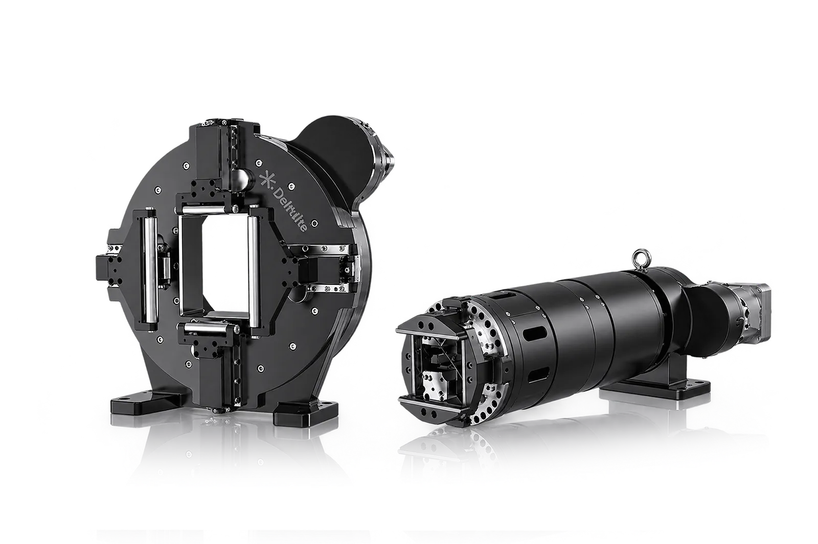
Two-chuck layout
The selected two-chuck arrangement defines gripping, indexing and transfer for the tube.
Check its exact envelope, load and remnant limits against the stock shape, length and weight.
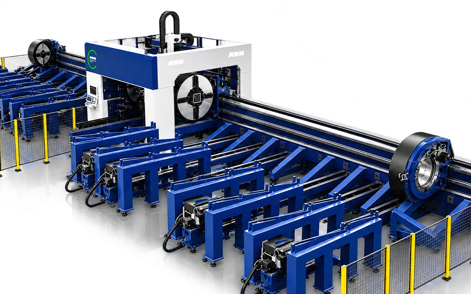
Three-chuck layout
In a three-chuck layout, the receiving chuck supports the workpiece as it passes the cutting head. For heavy sections or bevels, check where the chucks regrip, how the remaining length is supported, and whether the head clears the profile at the required angle. Use stock length and mass per metre to size the loading system.
Compare the exact machine data for the job. Chuck count, supplier and model are distinct configuration choices.
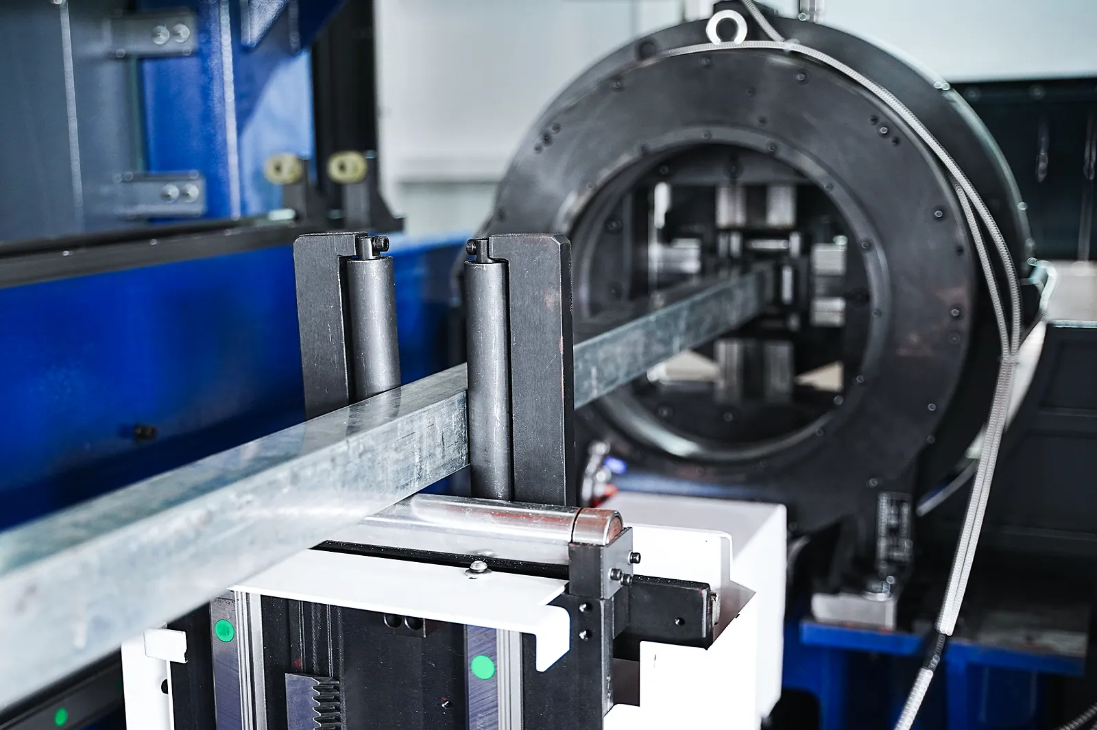
Stock support
Supports maintain the tube's presentation as it advances and rotates.
Match support to profile length and weight, including foundation and installation access.
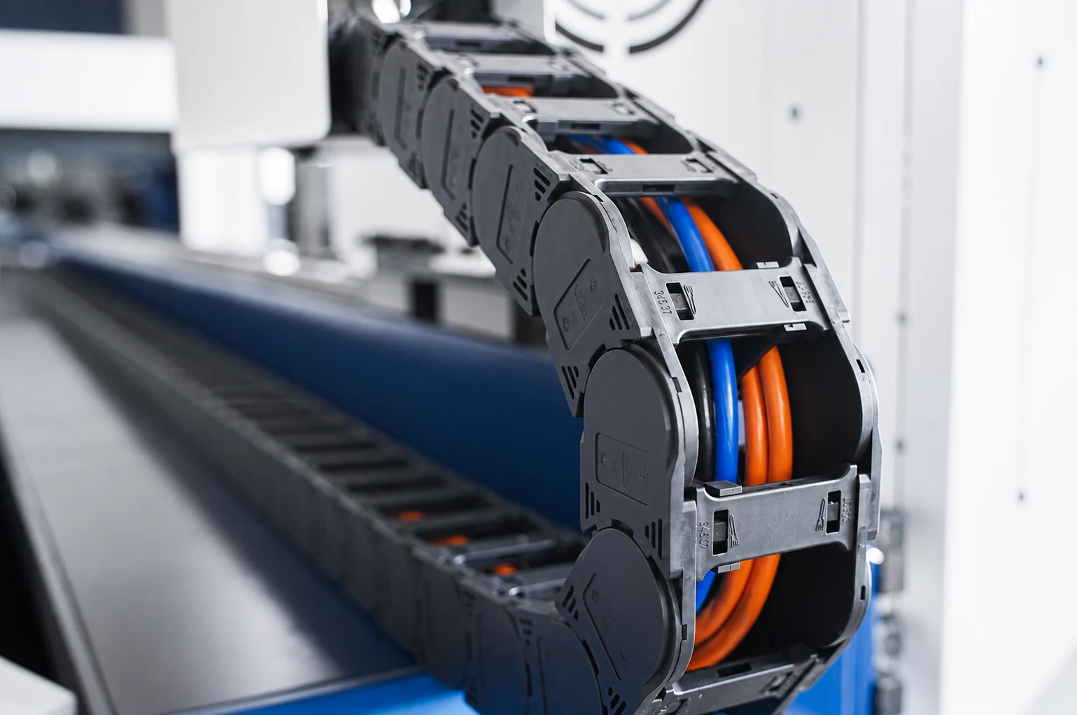
Coordinated motion
The transmission and motion system advance and rotate the profile through the sequence.
Use the selected model for travel, rotation, speed and load. Include remnant handling in the layout.
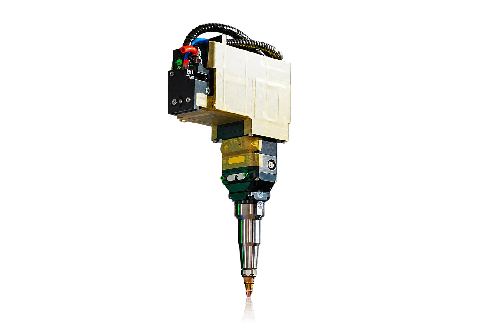
Tube cutting
Linear, rotary and height axes coordinate the cutting head with the tube.
Check the intended shapes and features with the actual mechanics. Bevel cutting and advanced axes require the corresponding configuration.
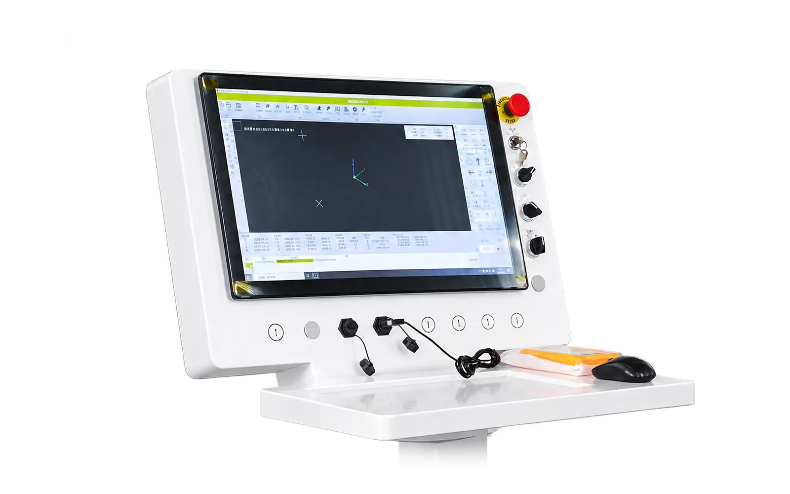
Program control
The supplied software manages the available nesting, compensation and chuck-avoidance functions.
Review the required program functions with the selected controller and machine architecture.
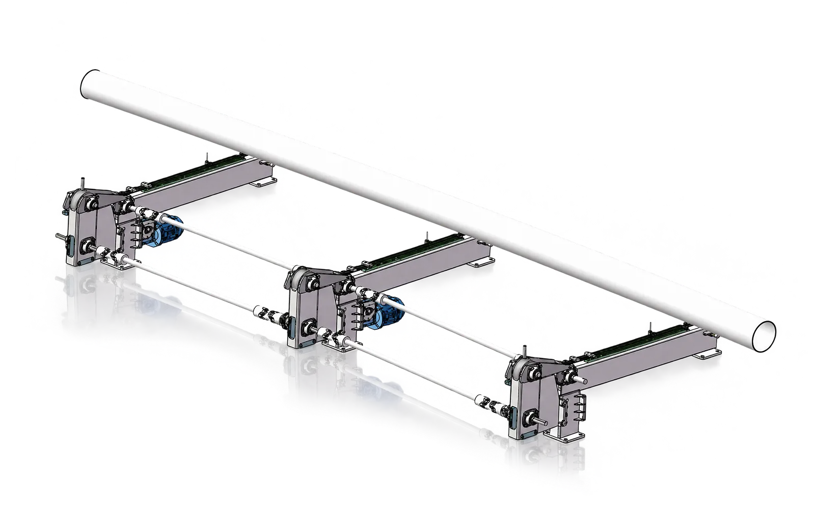
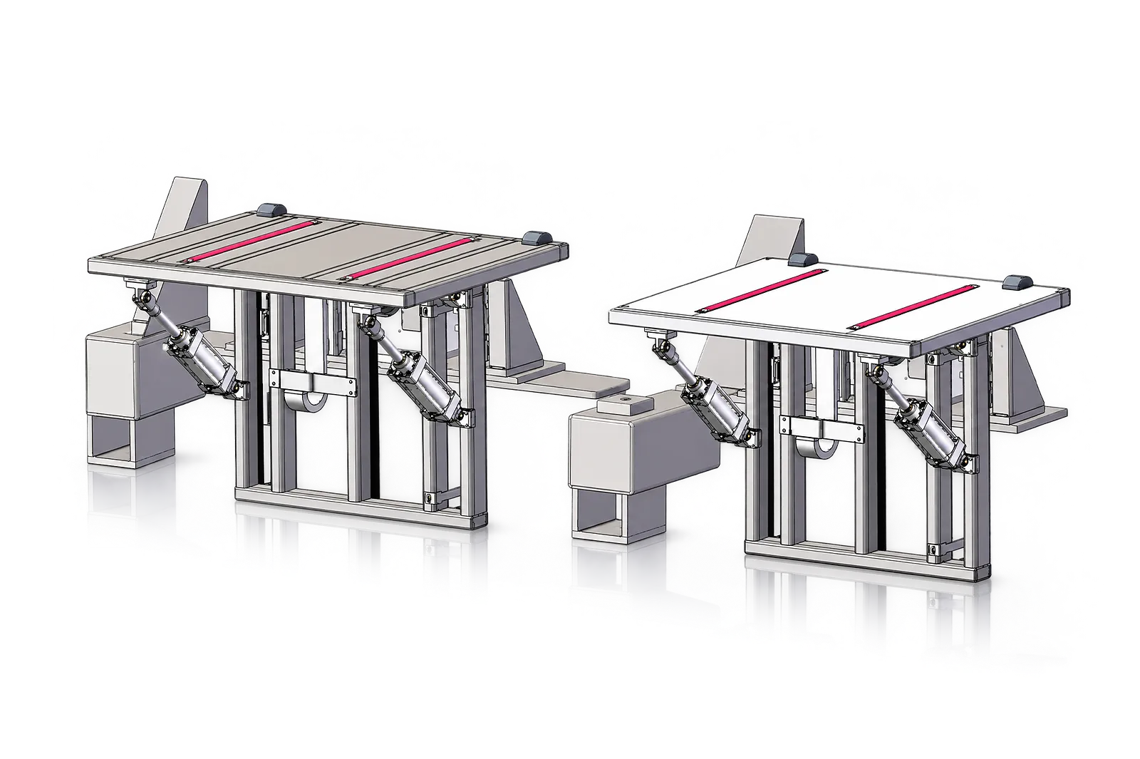
Feeding
Feeding is selected around stock length, weight and bundle condition.
Review pickup and support positions for the intended profiles and specify the feeding module.
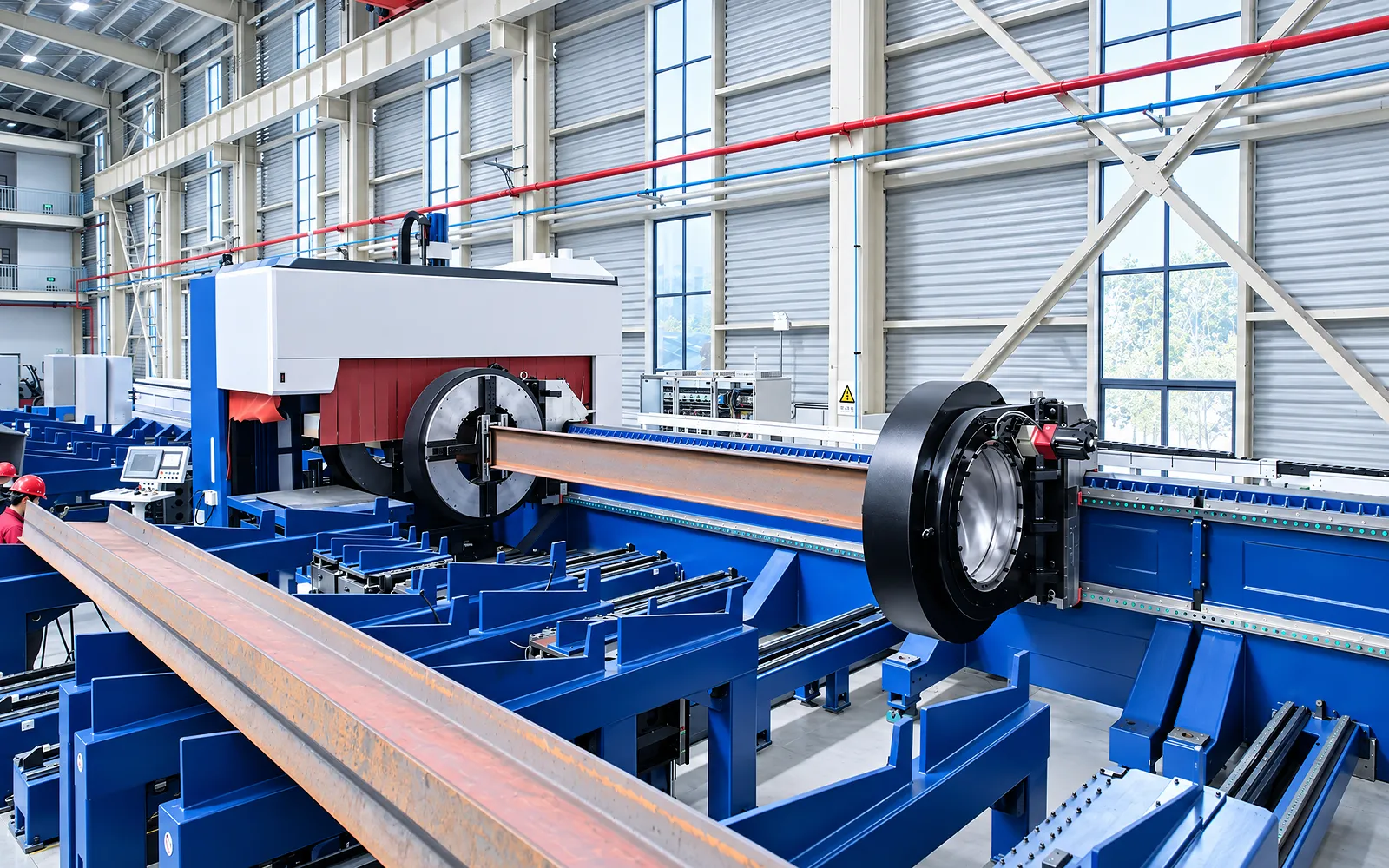
Unloading
Unloading is selected separately from feeding around finished-part length and collection needs.
Review output positions and define the unloading module's interface to the cutting machine.
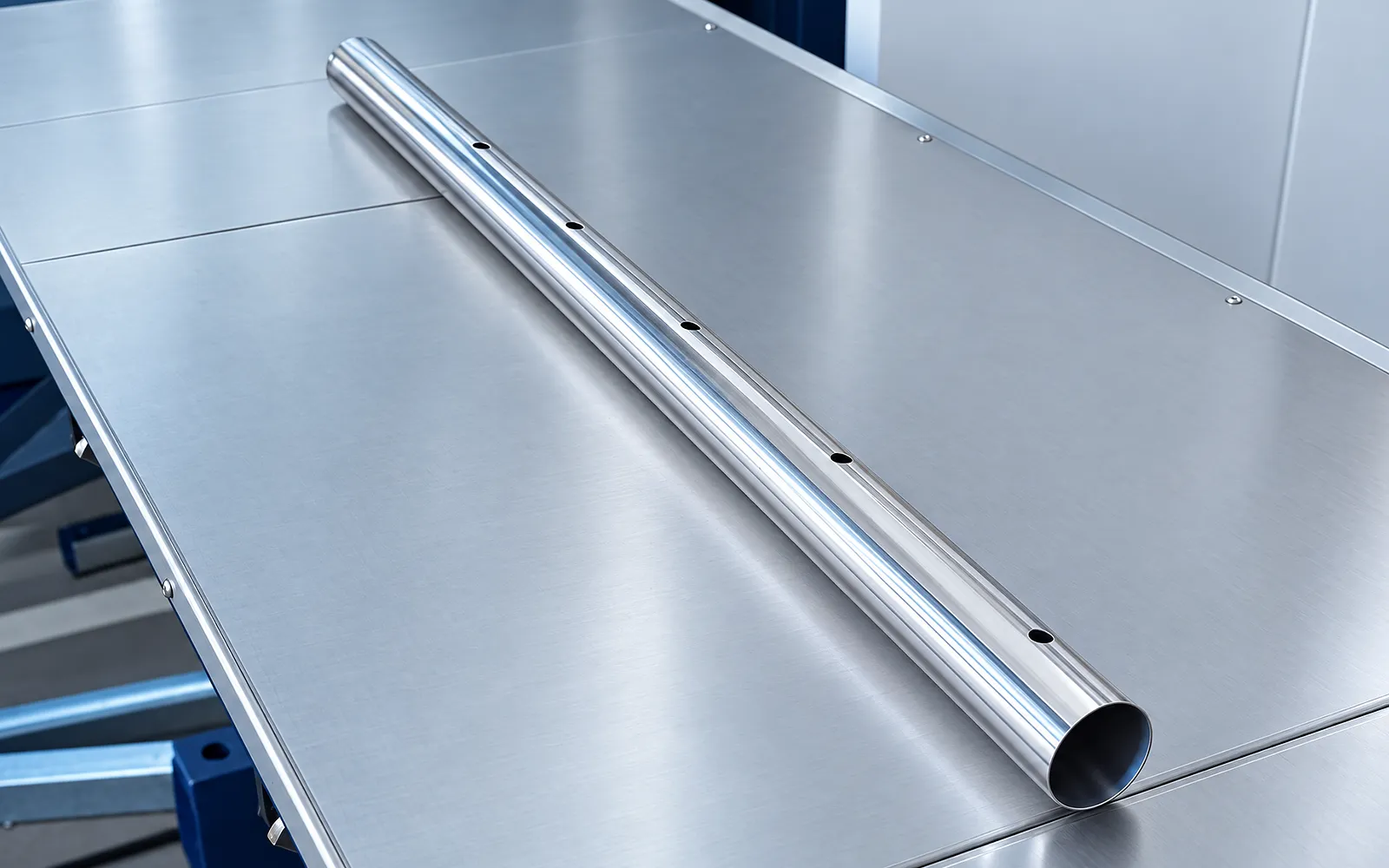
Profile trial
A representative profile exercises gripping, alignment, rotation and the complete cut sequence.
Use the agreed material and process setup; include loading and remnant handling.
Cut inspection
Inspect the profile features and finished dimensions against the drawing.
Agree the inspection criteria for the selected architecture without combining specifications from different layouts.
Model selection
Use one exact two- or three-chuck model column for tube range, motion, payload and dimensions.
Use one exact model column for tube range, travel, precision, speed, acceleration, chuck rotation, payload and dimensions.
Chuck package, bevel, supports, feeder, unloading, controller and software are project-dependent.
Confirm profile, wall, length, straightness, weight, remnant, handling, sample and safety.
Related machines & selection
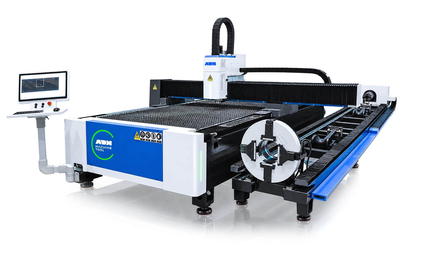
See how a Chinese contract manufacturer combined a separate tube laser and plate laser in its production route.
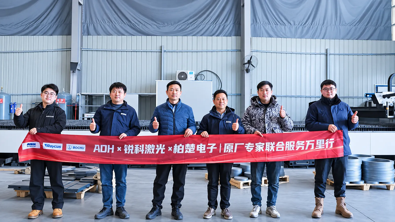
Contract manufacturing · Jiangsu, China
Combining 30 kW plate cutting and 12 kW tube cutting to broaden a contract manufacturer's production capability.
Through the machine lifecycle
Find the training, maintenance guidance and parts support your team needs. Services and availability are confirmed for your machine and location.
Before start-up
Prepare utilities, lifting and the installation area, then coordinate start-up and handover.
Review installation supportBefore production
Build the operator, programming and maintenance skills required for your delivered machine.
Explore trainingIn operation
Get support with the machine model, serial number and a clear description of the issue.
Request technical supportPlanned spares
Identify your machine and component so our team can check compatibility and availability.
Request service or partsSelf-service
Find video guidance for operating and maintaining your ADH machine. Check relevance to your model and configuration.
Browse support videosContract scope
Your quotation or contract defines included services, warranty, exclusions and responsibilities.
Review service scopeProject enquiry
Tell us what you want to make or improve. Technical details and drawings can follow.
Contact ADH
Name, email and a short description are enough to begin.