
01
Automatic upper-tool change
The active program assembles and positions segmented upper tools for the required working length.
Automatic Tool Change
Automatic upper-tool change for mixed-part panel production, with servo-electric forming and optional automated handling.
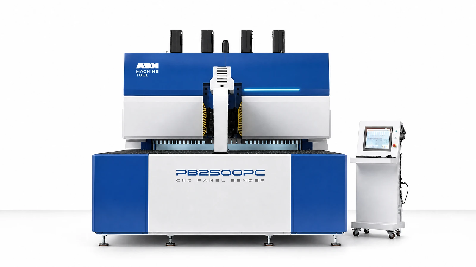
Technical specifications
Compare four PB-A models by maximum bend size, flange height, minimum inner dimensions and material thickness. The PB-A3200 accepts a maximum bend size of 3,200 × 1,200 mm. Check the starred limits against your material, tooling and bend sequence.
| Model | Max Thickness · 304 SS | Max Thickness · Cold-Rolled Steel | Max Thickness · Aluminium | Fastest Bend Time* | Max Bend Width | Bend Height | Rated Voltage | Total Power | Noise* | Min Material Thickness* | Min Four-Side Inner Size* | Min Two-Side Inner Size* | Max Bend Size* | Diagonal | Weight | Axes | Length | Width | Height |
|---|---|---|---|---|---|---|---|---|---|---|---|---|---|---|---|---|---|---|---|
| Unit | mm | mm | mm | s/bend | mm | mm | V | kW | dB | mm | mm | mm | mm | mm | t | count | mm | mm | mm |
| PB-A1630 | 1.5 | 2 | 3 | 0.2 | 1630 | 200 | 380 | ≈44 | ≈50 | ≈0.35 | 370×180 | 180 | 1630×1200 | 2340 | 12 | 26 | 4780 | 3110 | 2900 |
| PB-A2190 | 1.5 | 2 | 3 | 0.2 | 2190 | 200 | 380 | ≈89 | ≈50 | ≈0.35 | 370×180 | 180 | 2190×1200 | 2854 | 20 | 26 | 5700 | 3710 | 3200 |
| PB-A2610 | 1.5 | 2 | 3 | 0.2 | 2610 | 200 | 380 | ≈118 | ≈50 | ≈0.35 | 370×180 | 180 | 2610×1200 | 3240 | 24 | 26 | 6100 | 4140 | 3350 |
| PB-A3200 | 1.5 | 2 | 3 | 0.2 | 3200 | 200 | 380 | ≈165 | ≈50 | ≈0.35 | 390×200 | 200 | 3200×1200 | 3794 | 28 | 28 | 6950 | 4760 | 3500 |
At a glance
PB-A brings tool selection, servo motion and optional handling into one panel-bending workflow.
01
The active program assembles and positions segmented upper tools for the required working length.
02
Coordinated axes control panel feeding, positioning, rotation and bending.
03
Drawing import and simulation help prepare repeated panel work. Check tooling and interference on the intended part family.
04
Robot or gantry handling can be specified for pickup, rotation and transfer, with the required safeguarding and interfaces.
Machine in operation
Watch the PB-A3200 demonstration with gantry loading and unloading, then review the tool changes, blank handling and finished-panel flow for your application.
Watch on YouTube (opens in a new tab)Product systems
PB-A adds program-selected segmented tooling to a servo-electric panel-bending platform. Evaluate tool changes, panel motion and any external handling as one production sequence.
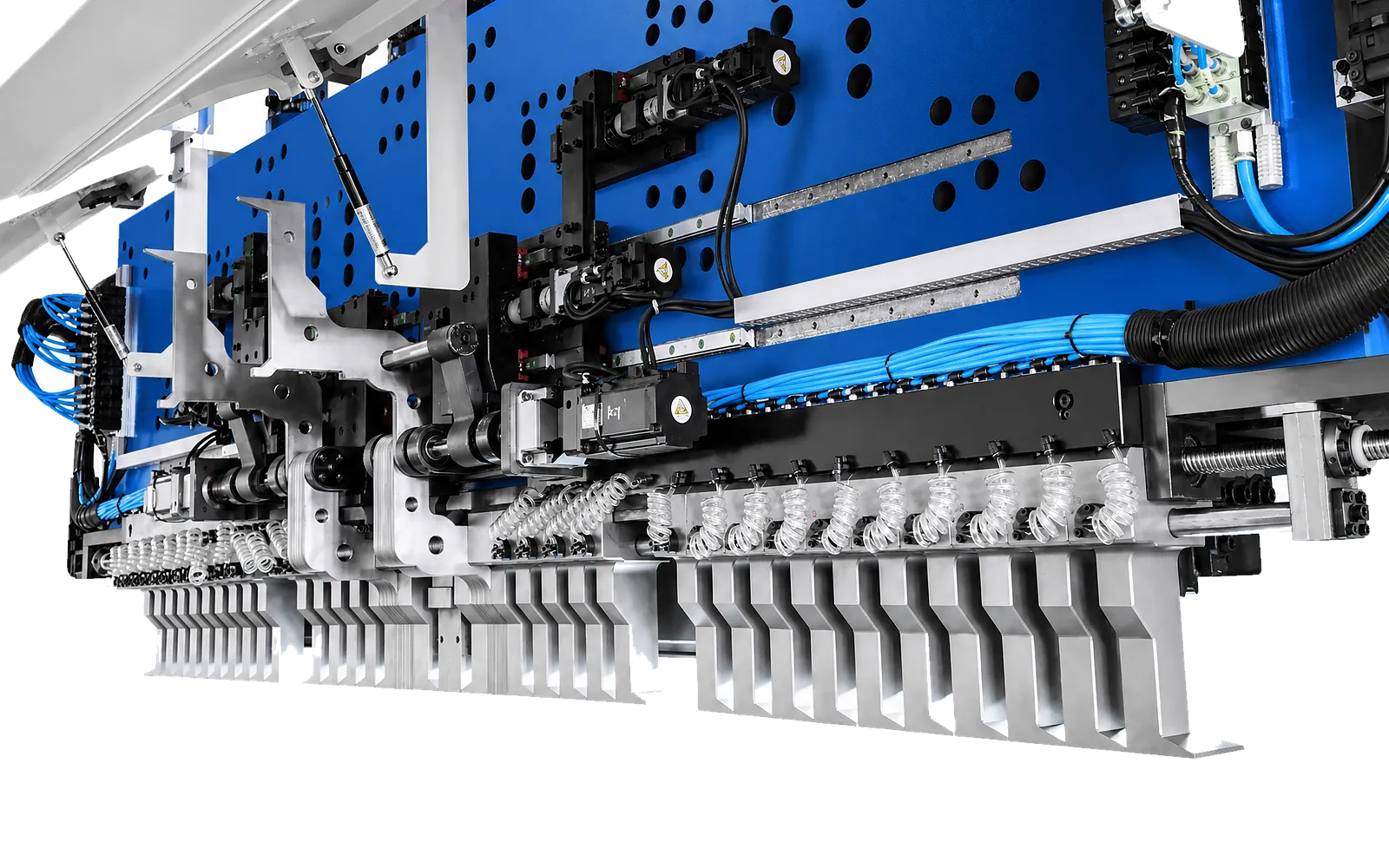
01
The active program assembles and positions segmented upper tools for the required working length. This reduces manual tool selection between compatible jobs.
Review segment inventory, tool combinations and flange clearance for the panel mix. Changeover time depends on the required arrangement and configuration.
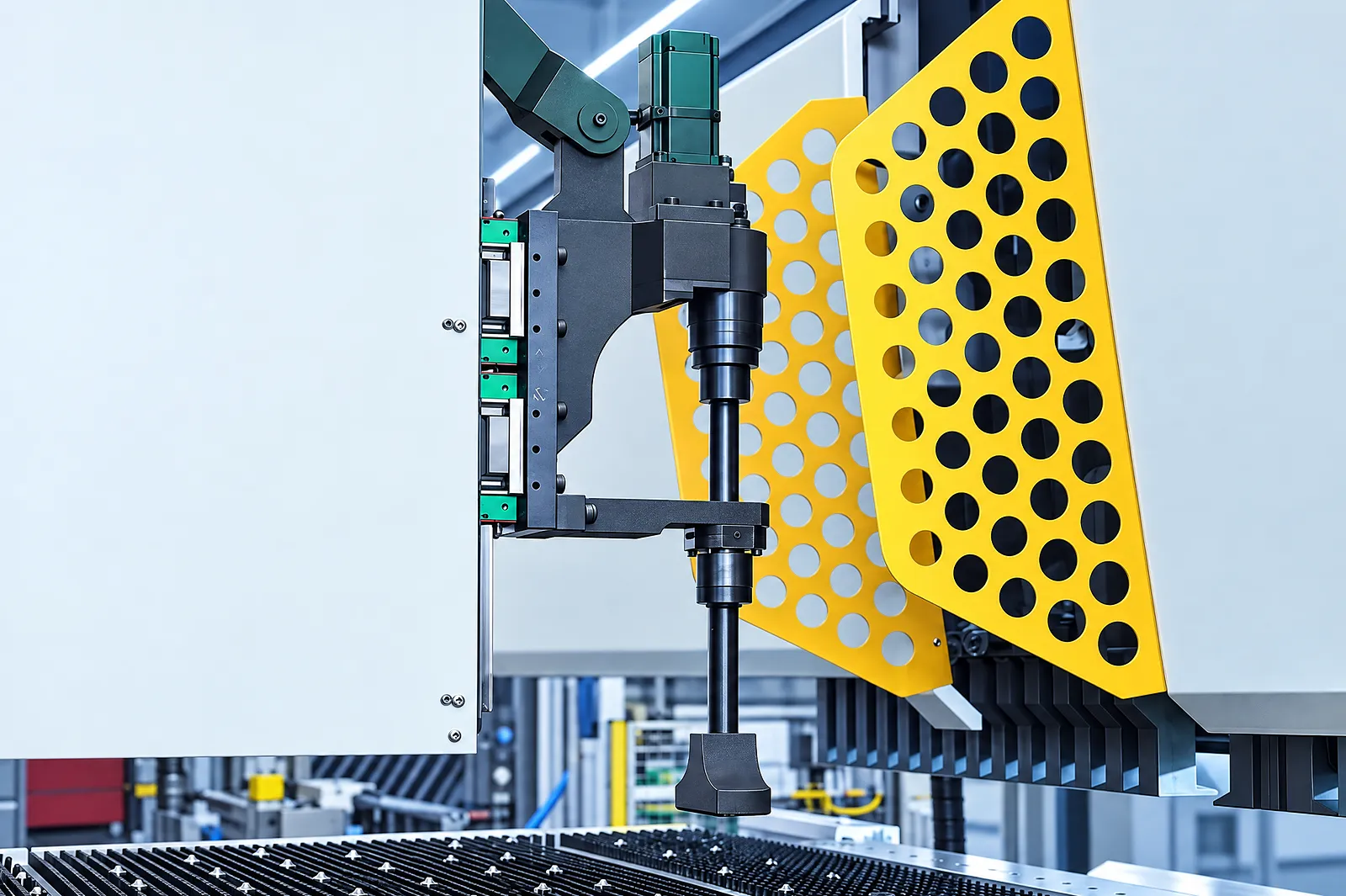
Feeding axes
Servo-electric axes coordinate feeding, positioning and rotation to present the panel for forming.
Choose the model around the panel envelope and test the required clearances.
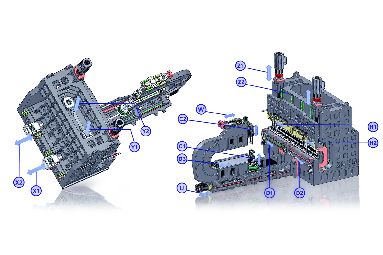
Forming axes
The forming sequence coordinates bending motion with program-selected tooling.
PB-A model data lists 26 or 28 axes depending on the machine. Review the functions of the selected package.
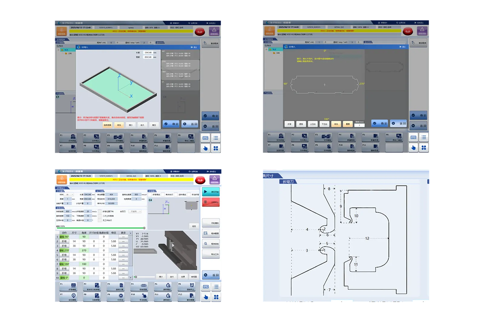
Drawing input
Drawing import connects panel geometry to program preparation within the supplied control package.
Confirm supported input and software functions for the intended panel family.
Sequence review
Sequencing and simulation support review of tool combinations, interference and compensation.
Demonstrate representative panels and confirm the process functions included in the delivered software.
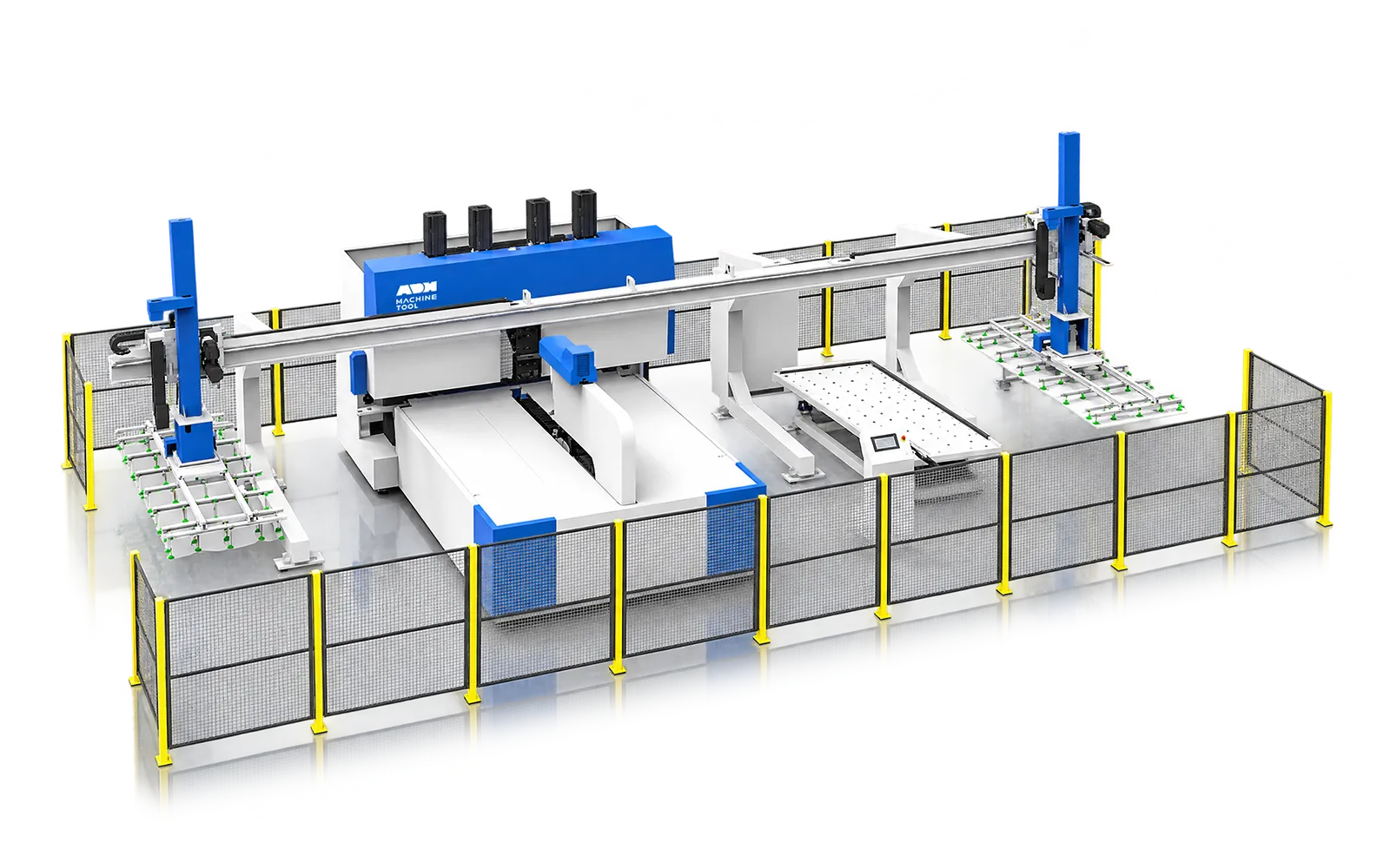
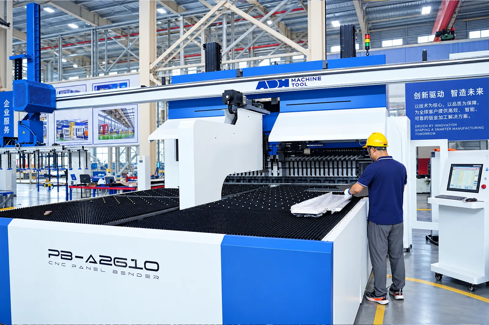
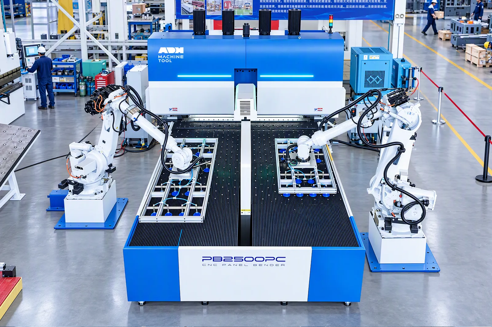
Optional loading
Robot or gantry handling can be configured for panel pickup, rotation and finished-part transfer.
Specify gripping, support and transfer needs for the intended parts.
Cell interfaces
MES/ERP, AGV and guarding interfaces connect the machine to the surrounding cell when configured.
Agree the required handshakes and responsibility for each equipment connection.
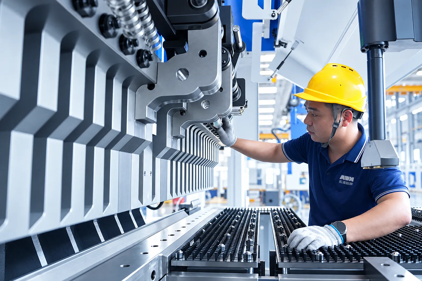
Tool maintenance
Inspect the tool segments and allow access to address damaged tooling and process debris.
Agree spare segments and the tool-maintenance documentation for the delivered model.
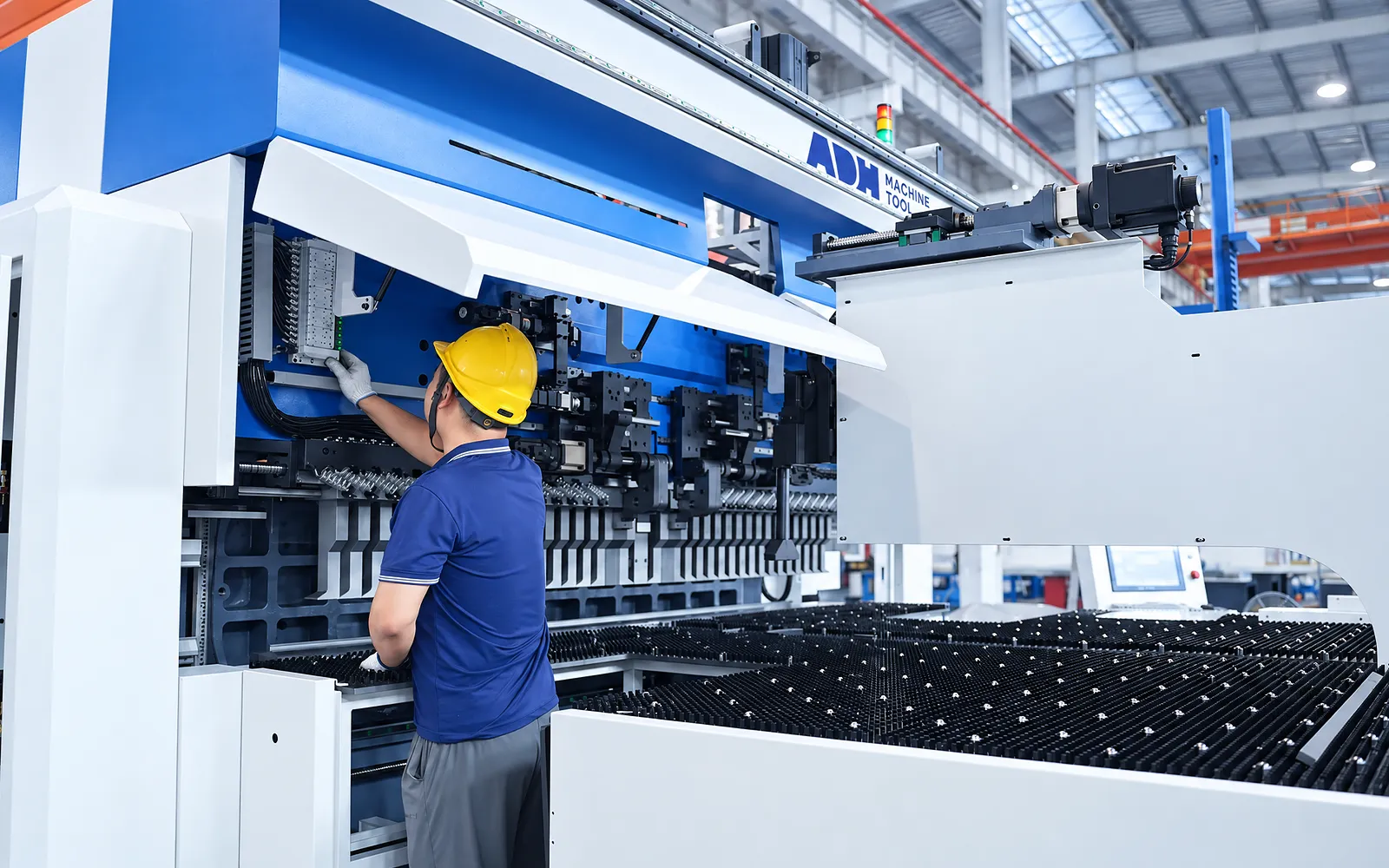
Motion-system maintenance
Sensor checks and axis references support repeat panel production.
Use the model-specific maintenance schedule and agree calibration and service access at handover.
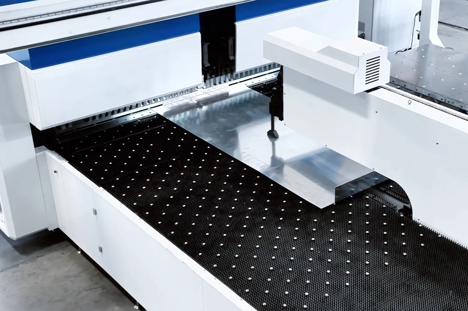
06
A representative panel family tests tool changes, bend order, transfer clearances and the finished-part result. Include changeovers and external handling where supplied.
Agree drawings, material, inspection points and interface tests. Evaluate the complete cycle rather than an isolated tool-change movement.
Configuration
Automatic tool change is the defining PB-A function; auxiliary tooling, handling and data integration are configuration-dependent.
Use the listed data for PB-A1630, A2190, A2610 and A3200; width, power, mass, axes and dimensions remain model-specific.
Specify auxiliary tools, robot or gantry handling, AGV and data interfaces as needed. Confirm the complete safeguarding arrangement for the cell.
Confirm panel geometry, tool combinations, interference, material limits, handling, changeover and sample acceptance.
Related machines & selection
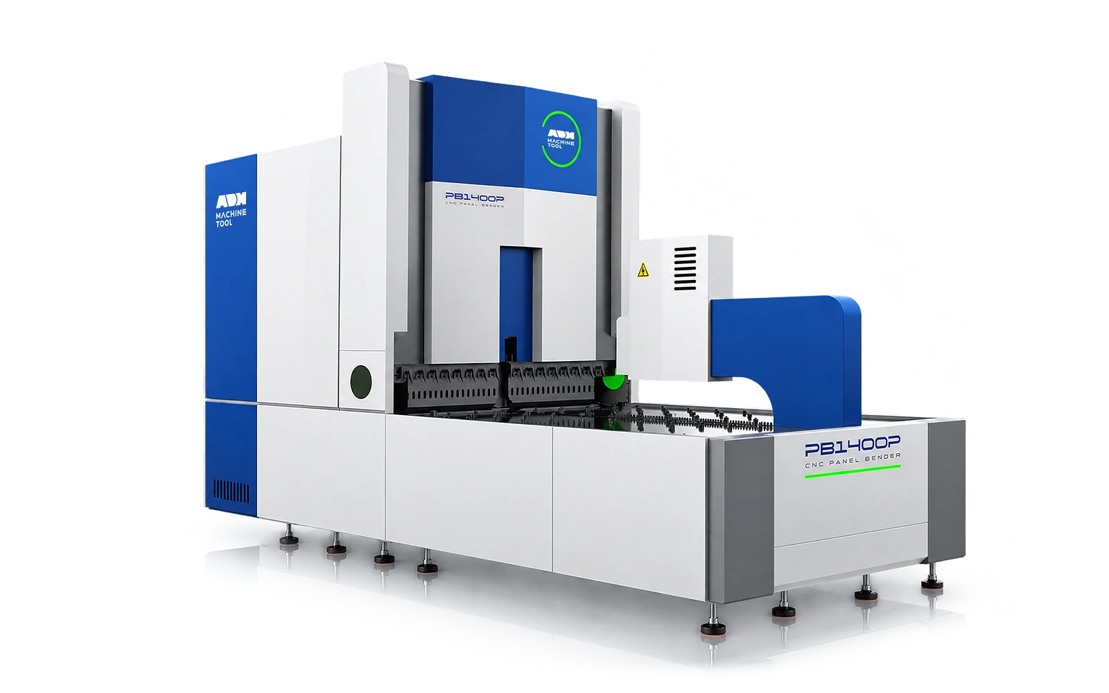
Through the machine lifecycle
Find the training, maintenance guidance and parts support your team needs. Services and availability are confirmed for your machine and location.
Before start-up
Prepare utilities, lifting and the installation area, then coordinate start-up and handover.
Review installation supportBefore production
Build the operator, programming and maintenance skills required for your delivered machine.
Explore trainingIn operation
Get support with the machine model, serial number and a clear description of the issue.
Request technical supportPlanned spares
Identify your machine and component so our team can check compatibility and availability.
Request service or partsSelf-service
Find video guidance for operating and maintaining your ADH machine. Check relevance to your model and configuration.
Browse support videosContract scope
Your quotation or contract defines included services, warranty, exclusions and responsibilities.
Review service scopeProject enquiry
Tell us what you want to make or improve. Technical details and drawings can follow.
Contact ADH
Name, email and a short description are enough to begin.