
Perforated panels
Repeated round or oblong holes can use one station throughout a pattern. Hole pitch, web width and sheet flatness determine the punching sequence.
Sheet punching · ES30P and M30P
Punch perforations, louvers and formed features in sheet metal. Compare the 300 kN ES30P and M30P by sheet thickness, tool layout and control axes.
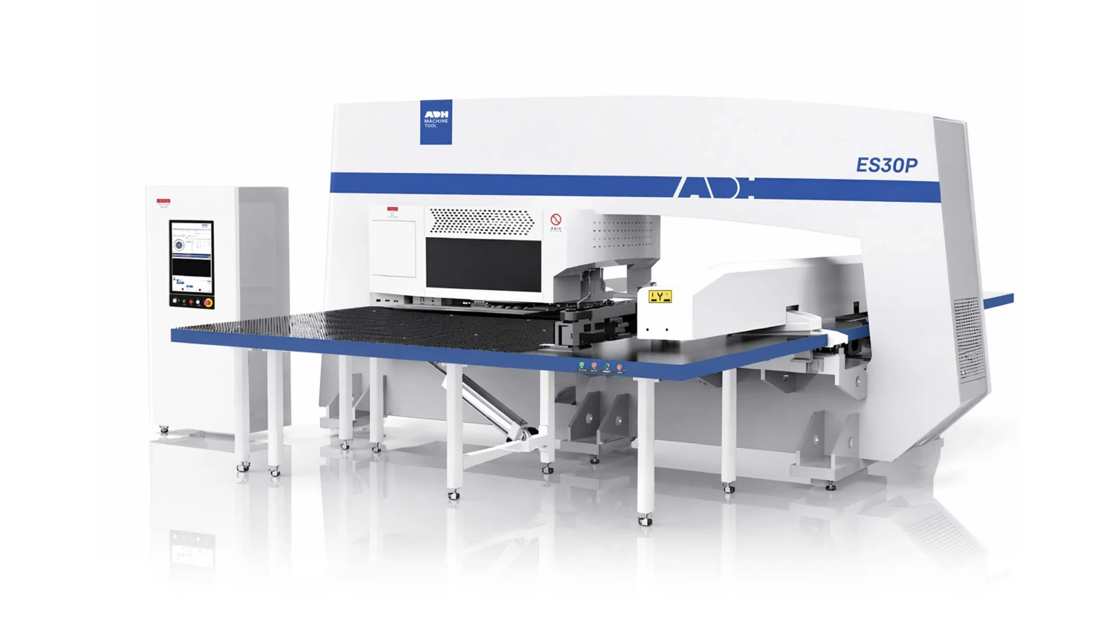
Technical specifications
These 300 kN configurations use a 32-station turret. The maximum X length includes one sheet reposition. Tool diameter and sheet thickness must be checked together against the material and the force available.
| Model | Press Capacity | Maximum Sheet Thickness | Maximum X With One Reposition | Maximum Tool Diameter | Punching Accuracy | Tool Stations in This Configuration | Control Axes | Air Pressure |
|---|---|---|---|---|---|---|---|---|
| Unit | kN | mm | mm | mm | mm | MPa | ||
| ES30P | 300 | 6.35 | 5000 | 88.9 | ±0.10 | 32 | 5 | 0.60 |
| M30P | 300 | 4 | 5000 | 88.9 | ±0.10 | 32 | 3 or 4 | 0.65 |
Applications
A turret punch is most useful when the same tool profile or formed feature appears repeatedly in the nest.
Repeated round or oblong holes can use one station throughout a pattern. Hole pitch, web width and sheet flatness determine the punching sequence.
A forming station can create a louver or emboss in one setup. Allow clearance for the raised feature on later tool passes and at unloading.
Group recurring holes by tool and reserve indexable stations for features at different angles. Compare irregular outer contours with laser cutting when deciding how to route a nest.
Check the largest nest against throat depth and reposition travel. Keep vulnerable cutouts clear of the clamps throughout the regrip.
Product systems
Tool selection, punch motion and sheet position meet at the same station. Each affects the finished feature.
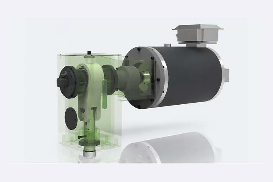
On the ES30P the servo motor drives the crank and connecting rod inside an O-frame. The tool perimeter, material strength and sheet thickness determine the load on each stroke.
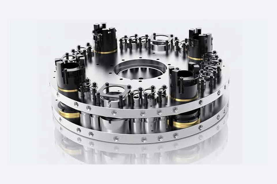
The turret holds paired punches and dies. Assign stations by tool size and use an indexing position when the same shape must punch at different angles. Custom turret layouts depend on the selected machine.
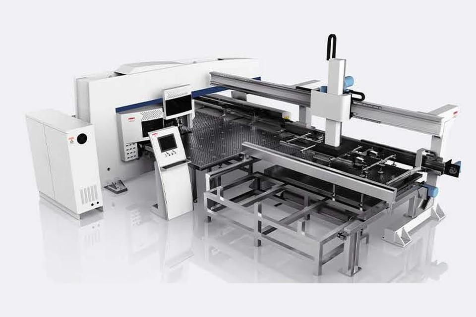
The feed axes move the clamped sheet across the support table. Repositioning extends the usable length. Plan clamp locations around the nest, especially where a final hit could release a part.
Sample parts
These examples show the difference between removing material and forming a feature out of the sheet.
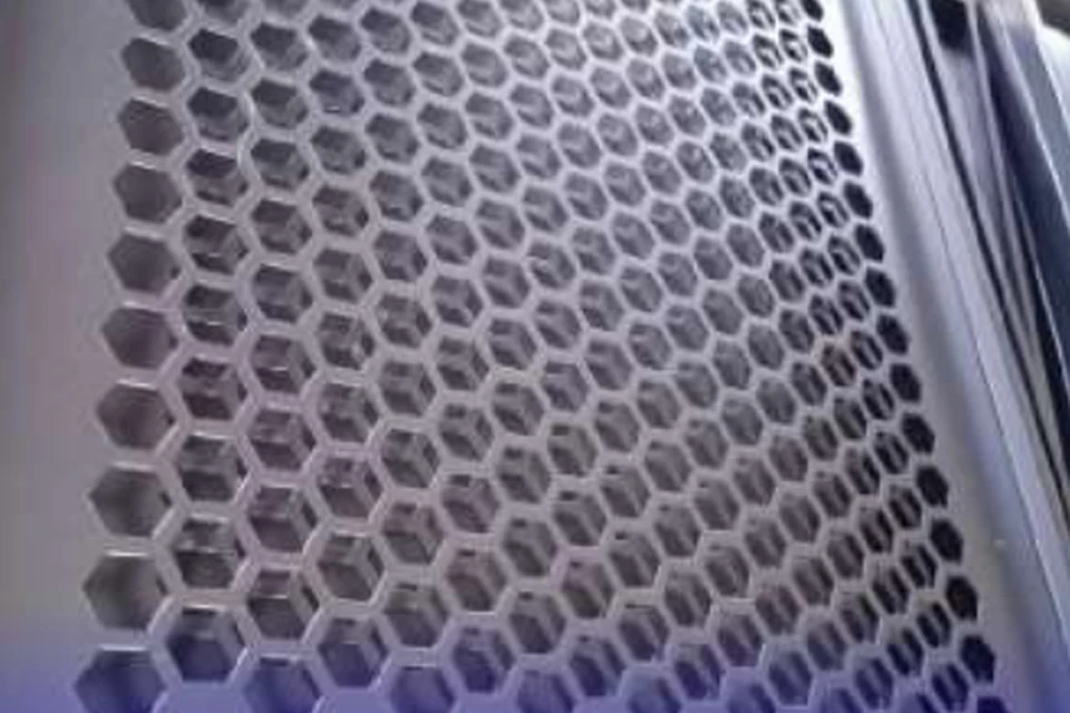
Web width between holes and the punching sequence affect how flat the grille stays.
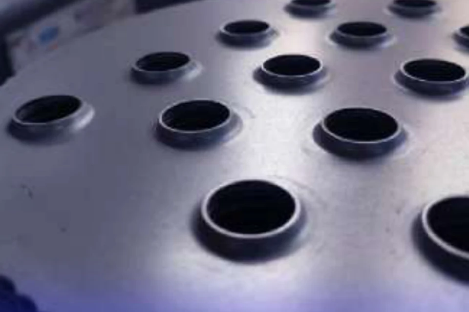
A forming tool draws a collar around the opening. Allow clearance for its height on the next tool pass.
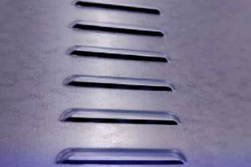
The louver tool cuts and forms the raised opening. Check its direction against the finished panel orientation.
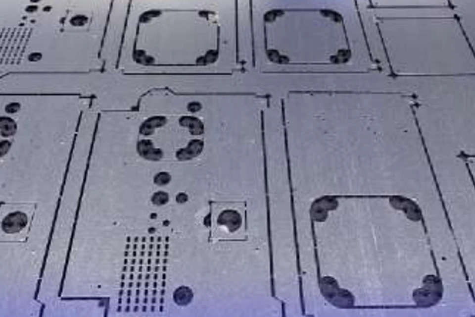
Different openings share a sheet. The clamp and regrip sequence must support each blank until release.
Configuration
Build the station list from the part drawings. The series includes custom 32- or 46-station layouts. Confirm the available layout for the selected model.
Select punch and die sizes for the material and burr direction. Include forming height, indexing needs and regrip positions in the nest.
For automated production, specify how sheets enter, which parts remain in the skeleton and how finished work and scrap leave the cell.
Through the machine lifecycle
Find the training, maintenance guidance and parts support your team needs. Services and availability are confirmed for your machine and location.
Before start-up
Prepare utilities, lifting and the installation area, then coordinate start-up and handover.
Review installation supportBefore production
Build the operator, programming and maintenance skills required for your delivered machine.
Explore trainingIn operation
Get support with the machine model, serial number and a clear description of the issue.
Request technical supportPlanned spares
Identify your machine and component so our team can check compatibility and availability.
Request service or partsSelf-service
Find video guidance for operating and maintaining your ADH machine. Check relevance to your model and configuration.
Browse support videosContract scope
Your quotation or contract defines included services, warranty, exclusions and responsibilities.
Review service scopeProject enquiry
Tell us what you want to make or improve. Technical details and drawings can follow.
Contact ADH
Name, email and a short description are enough to begin.